100%
B HOW TO USE THIS MANUAL
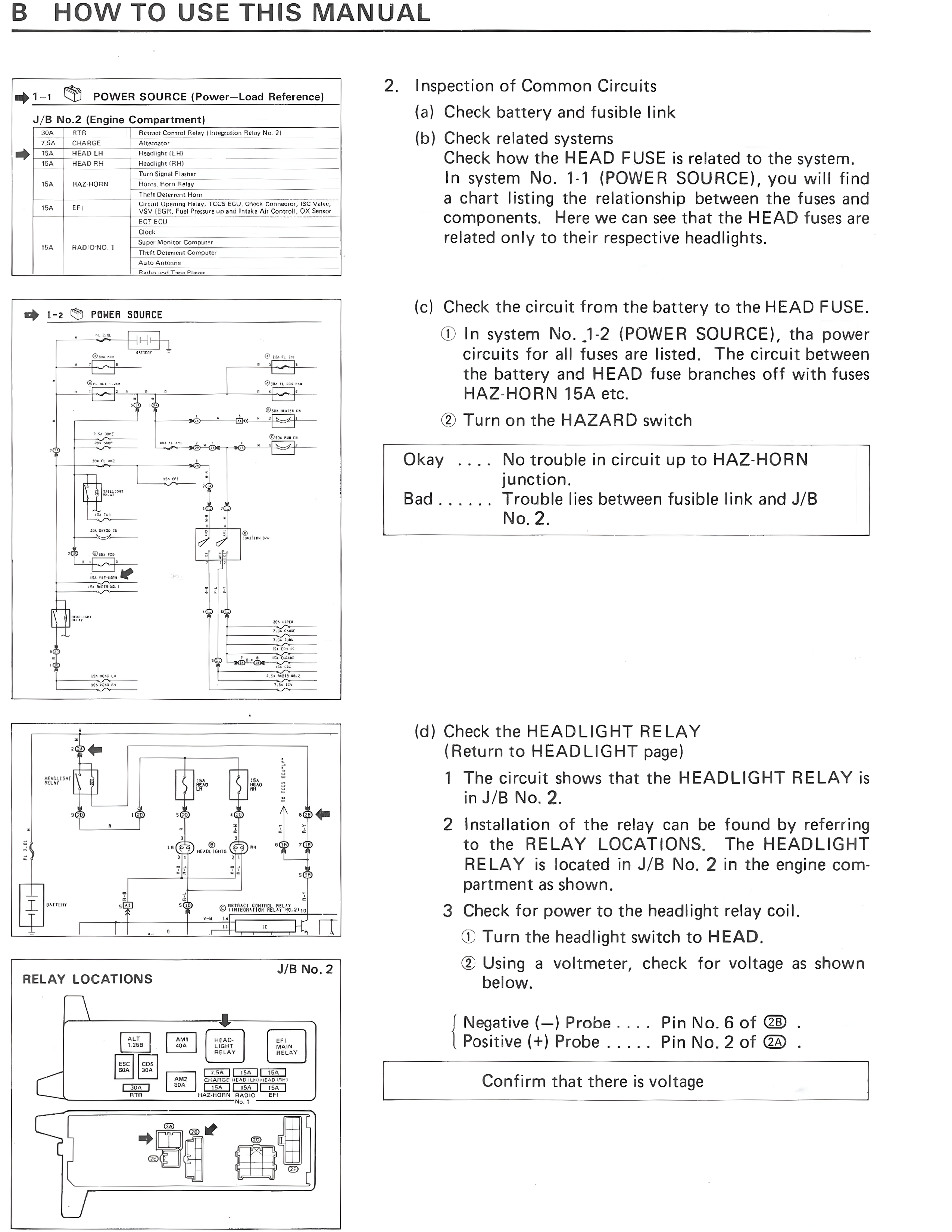
1-1 POWER SOURCE (Power-Load Reference)
J/B No.2 (Engine Compartment)
30A RTR Remain Illumination Relay No. 2)
P5A CHARGE Alternator
15A HEAD LH Headlight LH
15A HEAD RH Headlight RH
Turn Signal Flasher
Horn, Horn Relay
15A HAZ-HORN Hazard Switch
Fuel Pump
15A EFI Circuit Opening Relay, TCCS ECU, Crank Generator, ISC Valve, VSV, BVSV, Fuel Pressure-up VSV, Intake Air Control Valve Air Damper, O2 Sensor Main, DX Sensor
Clock
10A RAD O/PRD J Super Monitor Computer
Auto Antenna Computer
Auto Antenna
Radio and Turn Signal
1-2 POWER SOURCE
[Circuit diagram showing power distribution from battery through fuses]
J/B No. 2
RELAY LOCATIONS
[Diagram showing relay box layout with labels:
CHG RL
FUEL PMP RL
AWC RL
HEAD LIGHT RELAY
FAN RELAY MAIN
FAN RELAY SUB
FOG TAIL LIGHT CIRCUIT
INJ
NO. 1 FAN
IG COIL CIRCUIT OPENING
HAZ-HORN FLASHER
NO. 1 FAN
EFI]
2. Inspection of Common Circuits
(a) Check battery and fusible link
(b) Check related systems
Check how the HEAD FUSE is related to the system.
In system No. 1-1 (POWER SOURCE), you will find
a chart listing the relationship between the fuses and
components. Here we can see that the HEAD fuses are
related only to their respective headlights.
(c) Check the circuit from the battery to the HEAD FUSE.
① In system No. 1-2 (POWER SOURCE), tha power
circuits for all fuses are listed. The circuit between
the battery and HEAD fuse branches off with fuses
HAZ-HORN 15A etc.
② Turn on the HAZARD switch
Okay .... No trouble in circuit up to HAZ-HORN
junction.
Bad ...... Trouble lies between fusible link and J/B
No. 2.
(d) Check the HEADLIGHT RELAY
(Return to HEADLIGHT page)
1 The circuit shows that the HEADLIGHT RELAY is
in J/B No. 2.
2 Installation of the relay can be found by referring
to the RELAY LOCATIONS. The HEADLIGHT
RELAY is located in J/B No. 2 in the engine compartment as shown.
3 Check for power to the headlight relay coil.
① Turn the headlight switch to HEAD.
② Using a voltmeter, check for voltage as shown
below.
Negative (-) Probe .... Pin No. 6 of 2B.
Positive (+) Probe ..... Pin No. 2 of 2A.
Confirm that there is voltage