← p.115p.117 →
AT/Automatic Transmission — Location of Retainers, Clip, Pin, Check Balls, Strainers, Springs and Valves, page 116
116 / 144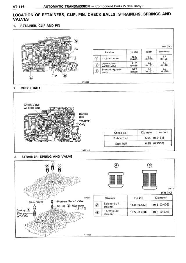
100%
Page text (OCR transcript)
AT-116

AUTOMATIC TRANSMISSION — Component Parts (Valve Body)

LOCATION OF RETAINERS, CLIP, PIN, CHECK BALLS, STRAINERS, SPRINGS AND VALVES

1. RETAINER, CLIP AND PIN

[Diagram showing valve body with labels A, B, C, Pin, Clip]

A73426

mm (in.)

Retainer | Height | Width | Thickness
A | 1-2 shift valve | 16.0 (0.650) | 6.0 (0.236) | 3.0 (0.120)
B | Accumulator control valve | 21.2 (0.835) | 5.0 (0.197) | 3.0 (0.120)
C | Primary regulator valve | 19.2 (0.756) | 5.0 (0.197) | 3.0 (0.120)

2. CHECK BALL

[Diagram showing check valve with steel ball and rubber ball locations]

Check Valve w/ Steel Ball

Rubber Ball
7M-GTE Only

A72348

Check ball | Diameter mm (in.)
Rubber ball | 5.54 (0.2181)
Steel ball | 6.35 (0.2500)

3. STRAINER, SPRING AND VALVE

[Diagram showing valve body with strainers, check valve, and pressure relief valve]

Check Valve
Spring A (See page AT-115)

Pressure Relief Valve
Spring B (See page AT-115)

D49908

A
B

A73296

A
B

D49614

mm (in.)

Strainer | Height | Diameter
A | Solenoid oil strainer | 11.0 (0.433) | 10.3 (0.406)
B | Throttle oil strainer | 19.5 (0.768) | 10.3 (0.406)