100%
AUTOMATIC TRANSMISSION — Shift Lock System AT-143
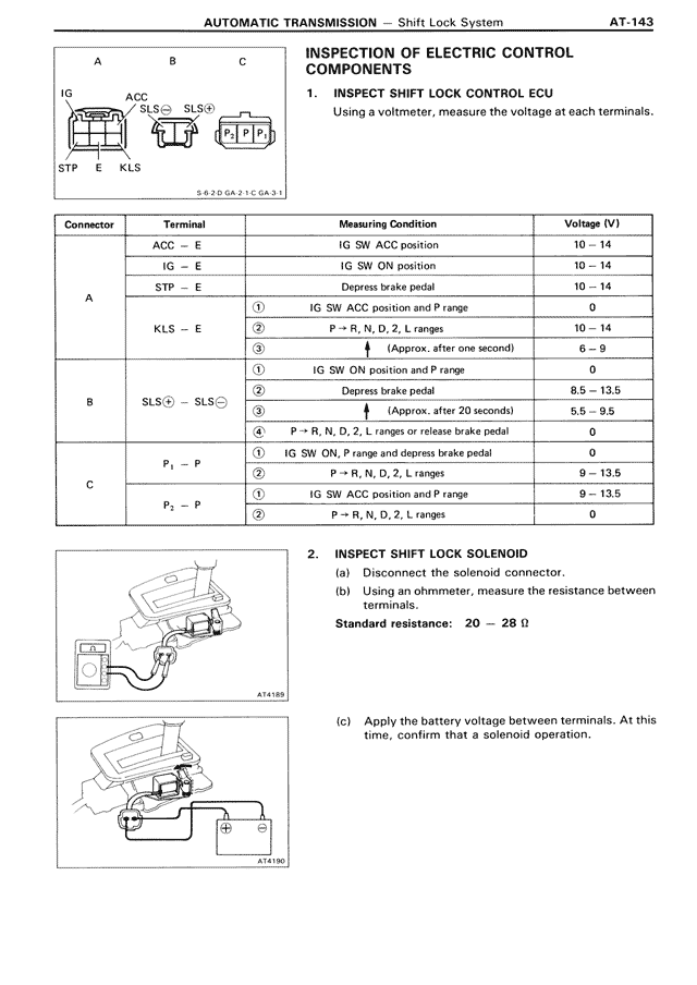
A B C
[Diagram showing connectors: IG, ACC, STP, E, KLS, SLS©, SLS①, P₁, P₂, P]
S.R.2-D GA 7 1C GA 3-1
INSPECTION OF ELECTRIC CONTROL COMPONENTS
1. INSPECT SHIFT LOCK CONTROL ECU
Using a voltmeter, measure the voltage at each terminals.
[THIS IS TABLE: Connector testing specifications with columns for Connector, Terminal, Measuring Condition, and Voltage (V)]
Connector | Terminal | Measuring Condition | Voltage (V)
A:
ACC — E | IG SW ACC position | 10 — 14
IG — E | IG SW ON position | 10 — 14
STP — E | Depress brake pedal | 10 — 14
① | IG SW ACC position and P range | 0
KLS — E | ② | P→R, N, D, 2, L ranges | 10 — 14
③ | ↓ (Approx. after one second) | 6 — 9
B:
① | IG SW ON position and P range | 0
SLS© — SLS① | ② | Depress brake pedal | 8.5 — 13.5
③ | ↓ (Approx. after 20 seconds) | 5.5 — 9.5
④ | P→R, N, D, 2, L ranges or release brake pedal | 0
C:
P₁ — P | ① | IG SW ON, P range and depress brake pedal | 0
② | P→R, N, D, 2, L ranges | 9 — 13.5
P₂ — P | ① | IG SW ACC position and P range | 9 — 13.5
② | P→R, N, D, 2, L ranges | 0
2. INSPECT SHIFT LOCK SOLENOID
(a) Disconnect the solenoid connector.
(b) Using an ohmmeter, measure the resistance between terminals.
Standard resistance: 20 — 28 Ω
[Diagram AT4189 showing ohmmeter testing]
(c) Apply the battery voltage between terminals. At this time, confirm that a solenoid operation.
[Diagram AT4190 showing battery connection test]