100%
GENERAL INFORMATION
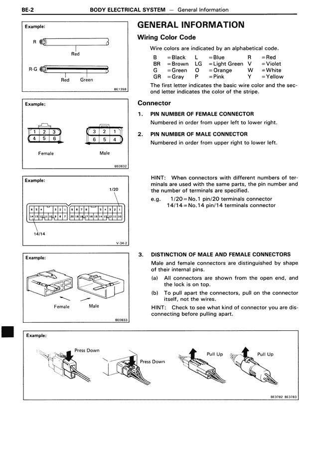
Wiring Color Code
Wire colors are indicated by an alphabetical code.
B = Black L = Blue R = Red
BR = Brown LG = Light Green V = Violet
G = Green O = Orange W = White
GR = Gray P = Pink Y = Yellow
The first letter indicates the basic wire color and the second letter indicates the color of the stripe.
Connector
1. PIN NUMBER OF FEMALE CONNECTOR
Numbered in order from upper left to lower right.
2. PIN NUMBER OF MALE CONNECTOR
Numbered in order from upper right to lower left.
HINT: When connectors with different numbers of terminals are used with the same parts, the pin number and the number of terminals are specified.
e.g. 1/20 = No.1 pin/20 terminals connector
14/14 = No.14 pin/14 terminals connector
3. DISTINCTION OF MALE AND FEMALE CONNECTORS
Male and female connectors are distinguished by shape of their internal pins.
(a) All connectors are shown from the open end, and the lock is on top.
(b) To pull apart the connectors, pull on the connector itself, not the wires.
HINT: Check to see what kind of connector you are disconnecting before pulling apart.
Example:
R [wire diagram]
Red
R G [wire diagram]
Red Green
BE1368
Example:
[Connector diagrams showing Female and Male connectors with numbered pins]
1 2 3
4 5 6
Female
3 2 1
0 5 4
Male
BE0632
Example:
1/20
[Detailed connector diagram showing pin numbering]
14/14
V-342
Example:
[Connector physical appearance diagrams]
Female Male
BE0633
Example:
[Connector disconnect/connect diagrams showing]
Press Down Press Down Pull Up Pull Up
BE3782 BE3793