100%
BE-22
BODY ELECTRICAL SYSTEM — Lighting System
Reference:
RIGHT TURN
FLASH
LO
HI
LEFT TURN
[CONNECTOR DIAGRAM]
BE2100
V.10-2
Parts Inspection
Headlight and Taillight System
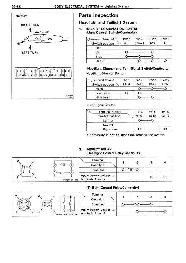
1. INSPECT COMBINATION SWITCH
(Light Control Switch/Continuity)
Terminal (Wire color) | 20/9 | 2/14 | 11/14 | 13/14
Switch position | (G) | (Clear) | (W) | (R)
OFF | | | |
UP | O—|—|—O
TAIL | O—|—O—|—|
HEAD | |—O—O—|—O
(Headlight Dimmer and Turn Signal Switch/Continuity)
Headlight Dimmer Switch
Terminal (Color) | 3/14 | 9/14 | 12/14 | 14/14
Switch position | (R-G) | (W-B) | (R-Y) | (R-W)
Flash | |—O—|—O—|—O
Low beam | O—|—O—|—|
High beam | |—O—|—O—|
Turn Signal Switch
Terminal (Color) | 1/14 | 5/14 | 8/14
Switch position | (G-W) | (G-B) | (G-Y)
Left turn | O—|—O—|
Neutral | | | |
Right turn | O—|—|—O
If continuity is not as specified, replace the switch.
2. INSPECT RELAY
(Headlight Control Relay/Continuity)
[RELAY DIAGRAM with numbered terminals 1-4]
Terminal | 1 | 2 | 3 | 4
Condition
Constant | O—/∩∩∩
Apply battery voltage to
terminals 1 and 2. | | | O—|—O
(Taillight Control Relay/Continuity)
[RELAY DIAGRAMS with numbered terminals 1-4]
BE1647 BE1576 BE1641
Terminal | 1 | 2 | 3 | 4
Condition
Constant | O—|—/∩∩∩—|—O
Apply battery voltage to
terminals 1 and 3. | | O—|—|—O