100%
BODY ELECTRICAL SYSTEM — Lighting System
BE-27
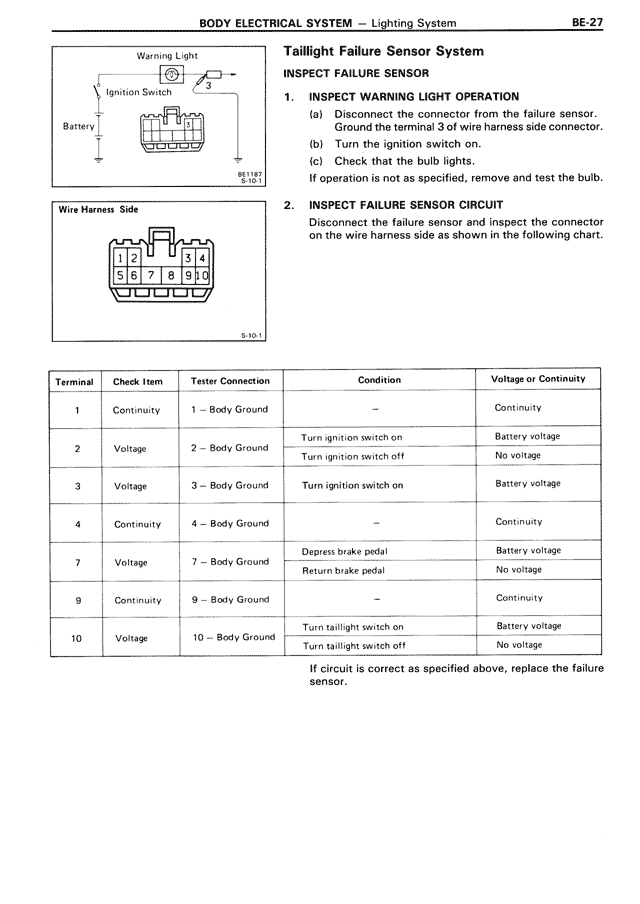
Taillight Failure Sensor System
INSPECT FAILURE SENSOR
1. INSPECT WARNING LIGHT OPERATION
(a) Disconnect the connector from the failure sensor. Ground the terminal 3 of wire harness side connector.
(b) Turn the ignition switch on.
(c) Check that the bulb lights.
If operation is not as specified, remove and test the bulb.
2. INSPECT FAILURE SENSOR CIRCUIT
Disconnect the failure sensor and inspect the connector on the wire harness side as shown in the following chart.
Warning Light
Ignition Switch
Battery
Wire Harness Side
[Connector diagram showing terminals 1-10]
[THIS IS TABLE: Terminal testing table with following columns: Terminal, Check Item, Tester Connection, Condition, Voltage or Continuity
Rows:
1 | Continuity | 1 — Body Ground | — | Continuity
2 | Voltage | 2 — Body Ground | Turn ignition switch on | Battery voltage
2 | Voltage | 2 — Body Ground | Turn ignition switch off | No voltage
3 | Voltage | 3 — Body Ground | Turn ignition switch on | Battery voltage
4 | Continuity | 4 — Body Ground | — | Continuity
7 | Voltage | 7 — Body Ground | Depress brake pedal | Battery voltage
7 | Voltage | 7 — Body Ground | Return brake pedal | No voltage
9 | Continuity | 9 — Body Ground | — | Continuity
10 | Voltage | 10 — Body Ground | Turn taillight switch on | Battery voltage
10 | Voltage | 10 — Body Ground | Turn taillight switch off | No voltage]
If circuit is correct as specified above, replace the failure sensor.