100%
BE-28
BODY ELECTRICAL SYSTEM — Lighting System
Test Bulb 3.4 W
12
11
10
9
3
BE0254
Test Bulb 3.4 W
12
11
10
9
3
BE0361
U.S.A.
OFF
1
2
3
4
BE3995
BE3994
CANADA
OFF
1
2
3
4
BE3916
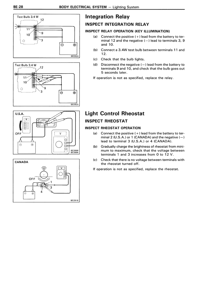
Integration Relay
INSPECT INTEGRATION RELAY
INSPECT RELAY OPERATION (KEY ILLUMINATION)
(a) Connect the positive (+) lead from the battery to terminal 12 and the negative (—) lead to terminals 3, 9 and 10.
(b) Connect a 3.4W test bulb between terminals 11 and 12.
(c) Check that the bulb lights.
(d) Disconnect the negative (—) lead from the battery to terminals 9 and 10, and check that the bulb goes out 5 seconds later.
If operation is not as specified, replace the relay.
Light Control Rheostat
INSPECT RHEOSTAT
INSPECT RHEOSTAT OPERATION
(a) Connect the positive (+) lead from the battery to terminal 2 (U.S.A.) or 1 (CANADA) and the negative (—) lead to terminal 3 (U.S.A.) or 4 (CANADA).
(b) Gradually change the brightness of rheostat from minimum to maximum, to check that the voltage between terminals 1 and 3 increases from 0 to 12 V.
(c) Check that there is no voltage between terminals with the rheostat turned off.
If operation is not as specified, replace the rheostat.