100%
WIPERS AND WASHERS
Troubleshooting
Problem | Possible cause | Remedy | Page Front Rear
Wipers do not operate or return to off position | WIPER fuse blown Wiper motor faulty Wiper switch faulty Wiring or ground faulty | Replace fuse and check for short Check motor Check switch Repair as necessary | BE-4 BE-33 BE-31 BE-4 BE-34 BE-34
Wipers do not operate in INT position | Wiper relay faulty Wiper switch faulty Wiper motor faulty Wiring or ground faulty | Check relay Check switch Check motor Repair as necessary | BE-31 BE-31 BE-33 BE-34 BE-34 BE-34
Washers do not operate | Washer hose or nozzle clogged Washer motor faulty Washer switch faulty Wiring faulty | Repair as necessary Replace motor Check switch Repair as necessary | BE-31 BE-34
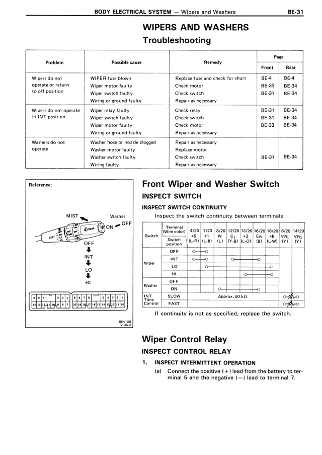
Reference:
[DIAGRAM OF WIPER SWITCH SHOWING MIST, Washer OUT, ON, OFF, INT positions with LO and HI settings]
Front Wiper and Washer Switch
INSPECT SWITCH
INSPECT SWITCH CONTINUITY
Inspect the switch continuity between terminals.
[TABLE SHOWING TERMINAL CONNECTIONS]
Switch Terminal (Wire color) Switch position | 4/20 +S (L-R) | 7/20 +1 (L-B) | 8/20 W (L) | 12/20 C1 (Y-B) | 13/20 L1 (L-O) | 16/20 B (B) | 18/20 L-W (L-W) | 8/20 V1 (Y) | 14/20 V2 (Y)
OFF | ○—○
Wiper INT | ○—○
LO | ○—○
HI | ○—○
Washer OFF |
ON | ○—○
Wind Time Control | SLOW | Approx. 50 kΩ
FAST | ○—○
If continuity is not as specified, replace the switch.
Wiper Control Relay
INSPECT CONTROL RELAY
1. INSPECT INTERMITTENT OPERATION
(a) Connect the positive (+) lead from the battery to terminal 5 and the negative (—) lead to terminal 7.