100%
8E-32 BODY ELECTRICAL SYSTEM — Wipers and Washers
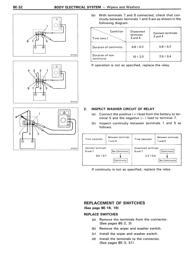
(b) With terminals 7 and 8 connected, check that continuity between terminals 1 and 5 are as shown in the following diagram.
Condition | Disconnect terminals 3 and 4 | Connect terminals 3 and 4
Time (secs.)
Duration of continuity | 0.8 ± 0.2 | 0.8 ± 0.2
Duration of non-continuity | 10 ± 2.0 | 2.0 ± 0.4
If operation is not as specified, replace the relay.
2. INSPECT WASHER CIRCUIT OF RELAY
(a) Connect the positive (+) lead from the battery to terminal 5 and the negative (–) lead to terminal 7.
(b) Inspect continuity between terminals 1 and 5 as follows.
Time (seconds) | Between terminals 1 and 5 | Time (seconds) | Between terminals 1 and 5
Connect terminals 6 and 7 | No Continuity | Disconnect terminals 6 and 7 | Continuity
0.5 ± 0.1 | Continuity | 2.5 ± 0.5 | No Continuity
If continuity is not as specified, replace the relay.
REPLACEMENT OF SWITCHES
(See page BE-18, 19)
REPLACE SWITCHES
(a) Remove the terminals from the connector.
(See pages BE-2, 3)
(b) Remove the wiper and washer switch.
(c) Install the wiper and washer switch.
(d) Install the terminals to the connector.
(See pages BE-3, 31)