100%
BE-34
BODY ELECTRICAL SYSTEM — Wipers and Washers
Reference
[Diagram showing switch connector]
WASH 1
WASH 2
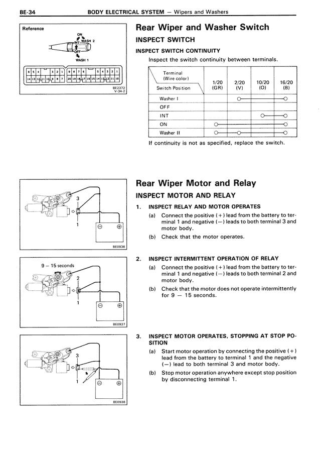
Rear Wiper and Washer Switch
INSPECT SWITCH
INSPECT SWITCH CONTINUITY
Inspect the switch continuity between terminals.
Terminal
(Wire color)
Switch Position
1/20
(GR)
2/20
(V)
10/20
(O)
16/20
(B)
Washer I
OFF
INT
ON
Washer II
If continuity is not as specified, replace the switch.
Rear Wiper Motor and Relay
INSPECT MOTOR AND RELAY
1. INSPECT RELAY AND MOTOR OPERATES
(a) Connect the positive (+) lead from the battery to terminal 1 and negative (—) leads to both terminal 2 and motor body.
(b) Check that the motor operates.
2. INSPECT INTERMITTENT OPERATION OF RELAY
(a) Connect the positive (+) lead from the battery to terminal 1 and negative (—) leads to both terminal 2 and motor body.
(b) Check that the motor does not operate intermittently for 9 — 15 seconds.
3. INSPECT MOTOR OPERATES, STOPPING AT STOP PO-SITION
(a) Start motor operation by connecting the positive (+) lead from the battery to terminal 1 and the negative (—) lead to both terminal 3 and motor body.
(b) Stop motor operation anywhere except stop position by disconnecting terminal 1.
[Three diagrams labeled BE0094, BE0097, and BE0098 showing wiper motor and relay test configurations]