100%
UNDER BODY
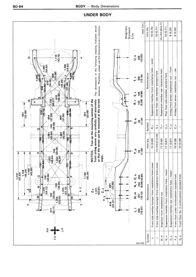
BO-64
BODY — Body Dimensions
NOTICE: First set up the mounting section of the
two way hydraulic jack indicated in the drawing, drawing, install
the proper plate and then check all dimensions. Install
the proper plate and then check all the dimension at its service
height.
RH
FR
LH
BO47B0
Dimension
between left
& right
L J
1624
(63.94)
N 6 m
1624
(63.74)
N 4 O
1574
(61.34)
P p
574
(22.60)
Q 4
1574
(61.34)
S 2
1574
(61.34)
U 4
1574
(61.34)
Member L
Front side member front installation hole
Member m
Side member front installation hole
Member n
Side member rear installation hole
Member O
A side rear installation hole
Member P
A rear quarter installation hole
Member Q
Suspension member rear installation hole
Member S
Suspension member front installation hole
Member U
A rear suspension support inner installation hole
19 (0.75)
19 (0.75)
mm (in.)
25 (0.98)
25 (0.98)
Front side member front member installation hole
9 (0.35)
9 (0.35)
A side front installation hole
Side member front installation hole
S1
O2
O1
Q2
19 (0.59)
19 (0.59)
15 (0.59)
15 (0.59)
11 (0.43)
11 (0.43)
17 (0.67)
17 (0.67)
10 (0.39)
10 (0.39)
Side member rear installation hole
A side rear installation hole
Suspension member front installation hole
Suspension member rear installation hole
A rear quarter installation hole
A rear suspension support inner installation hole
Front floor to front member installation hole
L
M
n
O
p
Q
S
Symbol