100%
BRAKE SYSTEM — Anti-lock Brake System (A.B.S.)
BR-69
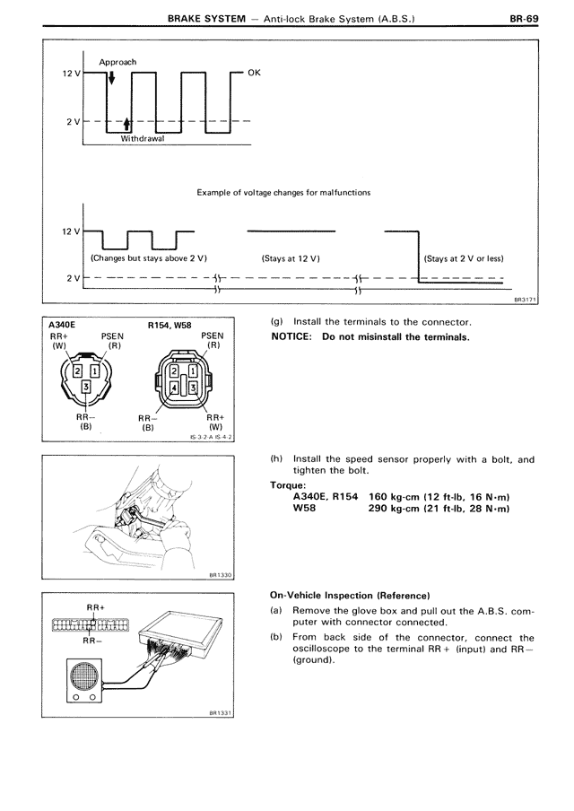
Approach
12 V
OK
2 V
Withdrawal
Example of voltage changes for malfunctions
12 V
(Changes but stays above 2 V)
(Stays at 12 V)
(Stays at 2 V or less)
2 V
BB3321
A340E
R154, W58
RR+
PSEN
PSEN
(W)
(R)
(R)
1
2
3
2
1
3
RR-
RR+
RR-
(B)
(B)
(W)
BC3-2 A & 3J
(g) Install the terminals to the connector.
NOTICE: Do not misinstall the terminals.
(h) Install the speed sensor properly with a bolt, and tighten the bolt.
Torque:
A340E, R154 160 kg-cm (12 ft-lb, 16 N-m)
W58 290 kg-cm (21 ft-lb, 28 N-m)
BB3320
On-Vehicle Inspection (Reference)
(a) Remove the glove box and pull out the A.B.S. computer with connector connected.
(b) From back side of the connector, connect the oscilloscope to the terminal RR+ (input) and RR— (ground).
RR+
RR-
BB3321