100%
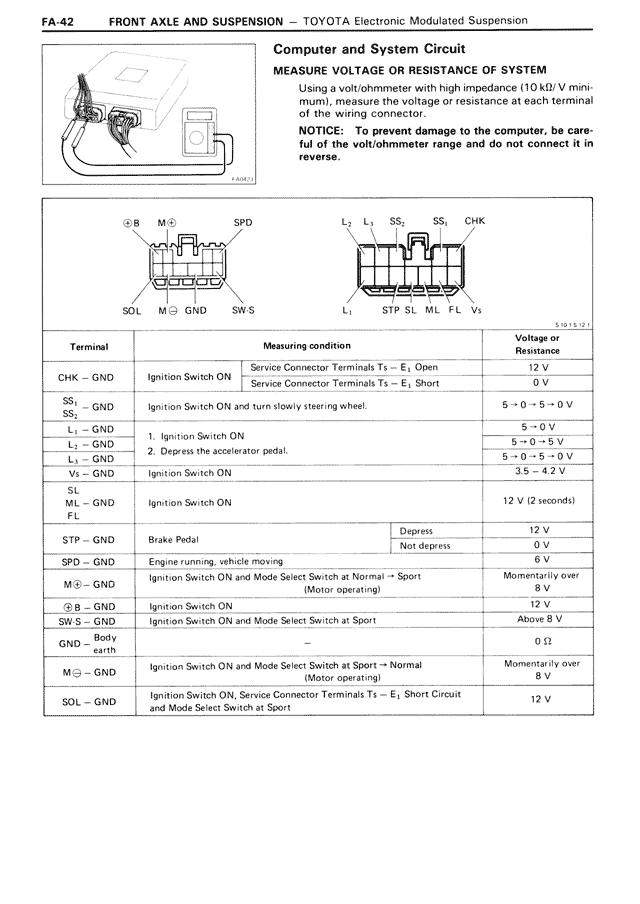
Computer and System Circuit
MEASURE VOLTAGE OR RESISTANCE OF SYSTEM
Using a volt/ohmmeter with high impedance (10 kΩ/V mini-
mum), measure the voltage or resistance at each terminal
of the wiring connector.
NOTICE: To prevent damage to the computer, be care-
ful of the volt/ohmmeter range and do not connect it in
reverse.
[Diagram showing computer connection and connector pinouts with labels: ⊕B, M⊖, SPD, SOL, M⊖, GND, SW·S on left connector; L₃, L₁, SS₁, SS₂, CHK, L₁, STP, SL, ML, FL, V₀ on right connector]
Terminal | Measuring condition | Voltage or Resistance
CHK - GND | Ignition Switch ON | Service Connector Terminals T₃ - E₁ Open: 12 V
Service Connector Terminals T₃ - E₁ Short: 0 V
SS₁
SS₂ - GND | Ignition Switch ON and turn slowly steering wheel. | 5→0→5→0 V
L₁ - GND | 1. Ignition Switch ON | 5→0 V
L₁ - GND | 2. Depress the accelerator pedal. | 5→0 V
L₃ - GND | | 5→0→5→0 V
V₀ - GND | Ignition Switch ON | 3.5→4.2 V
SL
ML - GND | Ignition Switch ON | 12 V (2 seconds)
FL
STP - GND | Brake Pedal | Depress: 12 V
Not depress: 0 V
SPD - GND | Engine running, vehicle moving | 6 V
M⊖ - GND | Ignition Switch ON and Mode Select Switch at Normal→Sport (Motor operating) | Momentarily over 8 V
⊕B - GND | Ignition Switch ON | 12 V
SW·S - GND | Ignition Switch ON and Mode Select Switch at Sport | Above 8 V
GND | Body earth | 0 Ω
M⊖ - GND | Ignition Switch ON and Mode Select Switch at Sport→Normal (Motor operating) | Momentarily over 8 V
SOL - GND | Ignition Switch ON, Service Connector Terminals T₃ - E₁ Short Circuit and Mode Select Switch at Sport | 12 V