100%
FI-40
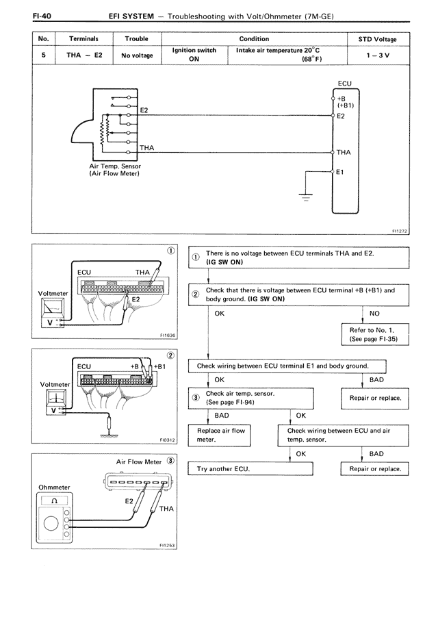
EFI SYSTEM — Troubleshooting with Volt/Ohmmeter (7M-GE)
No. | Terminals | Trouble | Condition | STD Voltage
5 | THA — E2 | No voltage | Ignition switch ON | Intake air temperature 20°C (68°F) | 1—3 V
[DIAGRAM: Circuit diagram showing Air Temp. Sensor (Air Flow Meter) with connections E2 and THA to ECU terminals +B (+B1) and E2, THA, E1]
[DIAGRAM 1: ECU connection showing THA terminal with voltmeter connection]
Text: There is no voltage between ECU terminals THA and E2. (IG SW ON)
[DIAGRAM 2: ECU connection showing +B (+B1) terminal with voltmeter connection]
Text: Check that there is voltage between ECU terminal +B (+B1) and body ground. (IG SW ON)
OK → NO → Refer to No. 1. (See page FI-35)
[DIAGRAM 3: ECU connection showing E1 terminal with ground connection]
Text: Check wiring between ECU terminal E1 and body ground.
OK → BAD
Check air temp. sensor. (See page FI-94) → Repair or replace.
BAD → OK
Replace air flow meter. → Check wiring between ECU and air temp. sensor.
OK → BAD
Try another ECU. → Repair or replace.
[DIAGRAM: Air Flow Meter with Ohmmeter connection between E2 and THA terminals]
FI1272
FI1636
FI0313
FI1253