Page text (OCR transcript)
MANUAL TRANSMISSION — Component Parts (Output Shaft Assembly)     MT-65

No. 2        No. 1
[Diagram showing clutch hub components]
Front ←
                                                   09615 D6644

ASSEMBLY OF OUTPUT SHAFT ASSEMBLY

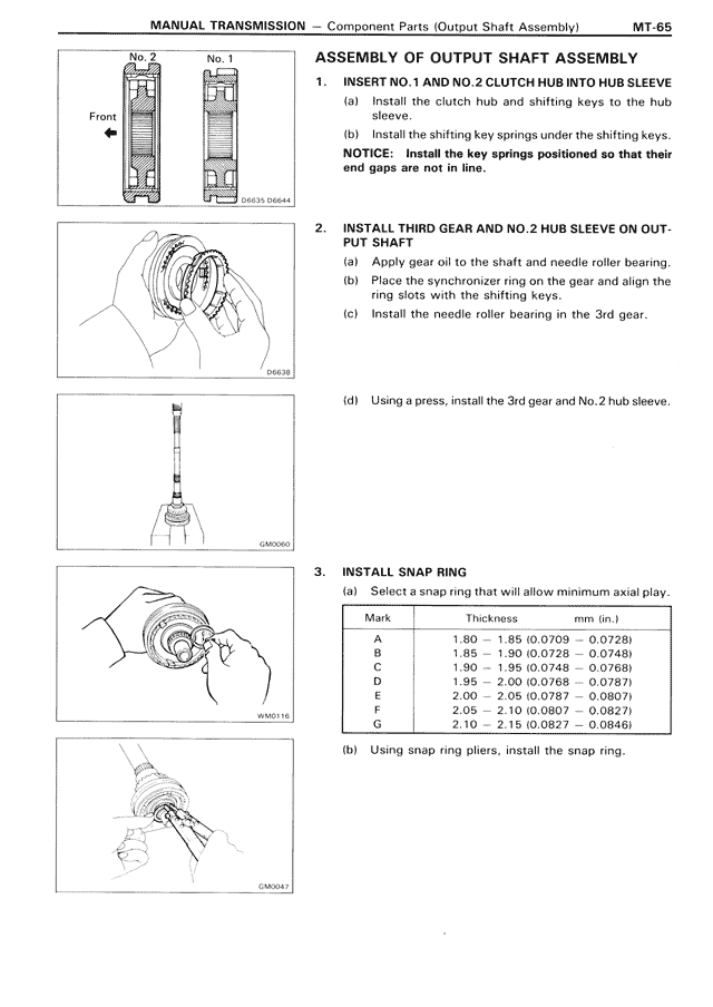
1. INSERT NO.1 AND NO.2 CLUTCH HUB INTO HUB SLEEVE
   (a) Install the clutch hub and shifting keys to the hub
       sleeve.
   (b) Install the shifting key springs under the shifting keys.
   NOTICE: Install the key springs positioned so that their
   end gaps are not in line.

2. INSTALL THIRD GEAR AND NO.2 HUB SLEEVE ON OUT-
   PUT SHAFT
   (a) Apply gear oil to the shaft and needle roller bearing.
   (b) Place the synchronizer ring on the gear and align the
       ring slots with the shifting keys.
   (c) Install the needle roller bearing in the 3rd gear.

[Diagram showing installation process]
09478

   (d) Using a press, install the 3rd gear and No.2 hub sleeve.

[Diagram showing press installation]
GA0005

3. INSTALL SNAP RING
   (a) Select a snap ring that will allow minimum axial play.

[Table showing snap ring specifications]
Mark    Thickness                        in. (mm)
A       1.80 — 1.85 (0.0709 — 0.0728)
B       1.85 — 1.90 (0.0728 — 0.0748)
C       1.90 — 1.95 (0.0748 — 0.0768)
D       1.95 — 2.00 (0.0768 — 0.0787)
E       2.00 — 2.05 (0.0787 — 0.0807)
F       2.05 — 2.10 (0.0807 — 0.0827)
G       2.10 — 2.15 (0.0827 — 0.0846)

   (b) Using snap ring pliers, install the snap ring.

[Diagram showing snap ring installation]
GAN0176

[Diagram showing snap ring pliers use]
GA0007