100%
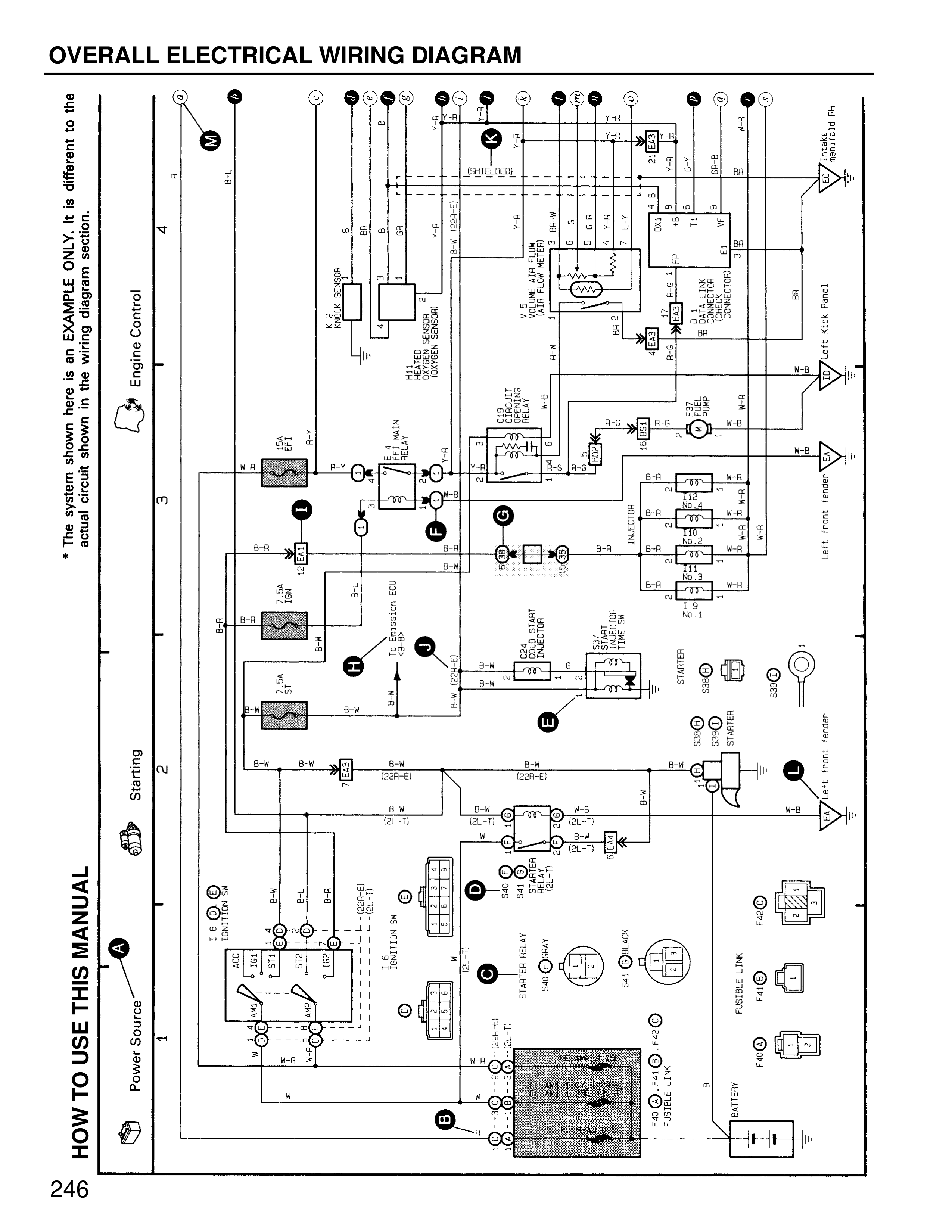
OVERALL ELECTRICAL WIRING DIAGRAM
* The system shown here is an EXAMPLE ONLY. It is different to the actual circuit shown in the wiring diagram section.
ONLY. It is different to the actual circuit shown in the wiring diagram section.
HOW TO USE THIS MANUAL
Power Source:
1
Starting
2
3
4
Engine Control
IG COIL N-B
IG COIL B
STATER MOTOR
B-W
B-W
B-W
B-W
B-R
B-R
B-R
B-R
A/C
IG1
IG2
ST1
ST2
IG COIL R
IG SWITCH ECU
BATTERY
STARTER RELAY
ST-2
ST-1
CL-T
CL-T
CL-T
CL-T
B-W
B-W
CG1-E
CG1-E
M-B
M-B
M-B
M-B
CL-T
CL-T
B
R-Y
R-Y
TAIL LIGHT CIRCUIT RELAY
VACUUM SENSOR LOWER SENSOR
THROTTLE POSITION SENSOR
VAVE & MAP SENSOR
ECU
SUB ASSY
R2-LV
R1-LY
IGNITION COIL
STARTER
S15
S16
S17
S18
S19
S20
S-11
ECU R1 CONNECTION CONTROL ENGINE
INJECTOR No.1
SUB-FR-RELAY
SH-RY
SUB-RY
FUSIBLE LINK
FM-B
F-11
F-12
F-13
LH FRONT FENDER
RH FRONT FENDER
246