100%
OVERALL ELECTRICAL WIRING DIAGRAM
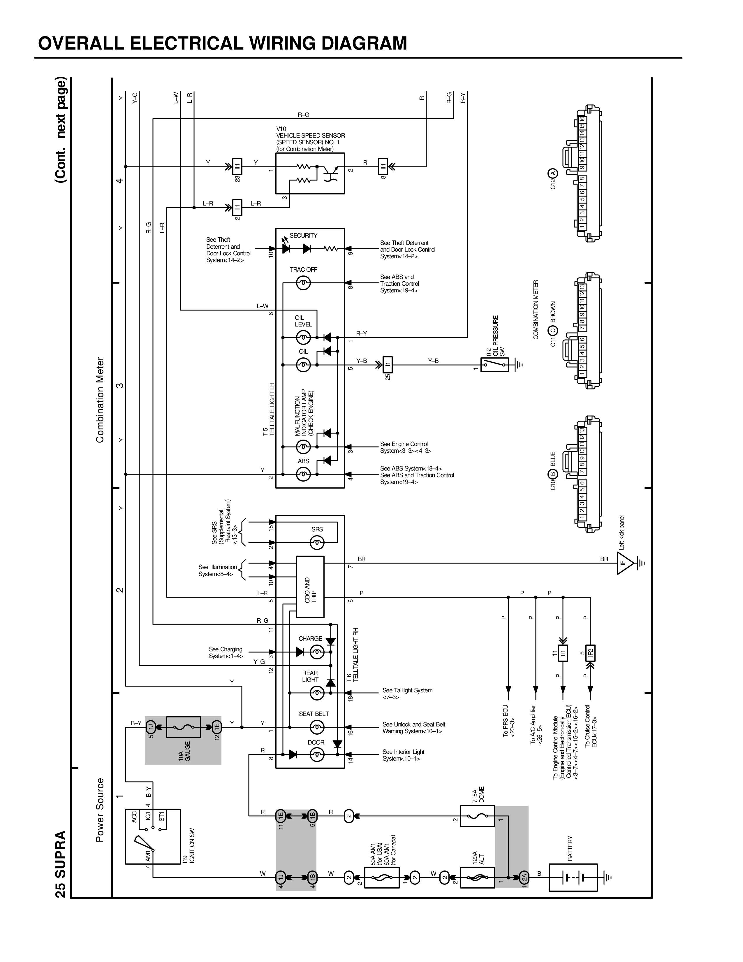
(Cont. next page)
25 SUPRA
Power Source
Combination Meter
VD
VEHICLE SPEED SENSOR
(SPEED SENSOR NO. 1)
IG-4~,JG-10~
Y
L-R
Y
L-R
See Theft Deterrent
and Door Lock Control
System-13-6~
SECURITY
TRAC OFF
L-W
OIL
LEVEL
R-Y
Y-B
MAGNETIC
CLUTCH RELAY
(A/C RELAY)
See Theft Deterrent
and Door Lock Control
System-13-6~
See ABS and
Traction Control
System-18-4~
Y-B
R-G
P-R
R
L-W
L-R
B-R
L-G
L-R
COMBINATION METER
C13 (A/C)
C13 (M/T)
C12 (A/C)
COMBINATION METER
OIL PRESSURE
See Engine Control
System-3-3~,4-3~
See ABS System-18-4~
See ABS and Traction Control
System-18-4~
SPS
BR
See Illumination
System-8-4~
L-R
ECT ECU
ECT AND
BR
P
P
P
R-G
P
P
P
P
CHARGE
TO TAILLIGHT RH
REAR
LIGHT
Y-G
See Charging
System-1-4~
V
See Taillight System
-7-3~
SEAT BELT
B-Y
Y
Y
See Unlock and Seat Belt
Warning System-10-1~
R
IGN SW
B-W
LOCK
IG
ACC START
R
See Interior Light
System-10-1~
BATTERY
C1
C3
C2
DLY SW
W
W
B
COA
FUSIBLE
LINK
SLM SW
(MIDDLE
SWITCH)
SLM SW
W
DIMER
SW
ELEV
RELAY
W
B
To Supra Combination
Meter Connector C12 or C13
-2~,3~,and Combination
Meter-1~,2~,3~
SPS-SCJ
SPS-2~
YOB Information
System-13-4~
To Supra Combination
Meter Connector C12
or C13-2~,3~
To Supra Combination
Meter Connector
C12-3~