100%
SRS (SUPPLEMENTAL RESTRAINT SYSTEM)
The supplemental restraint system has connectors which possess the functions described below:
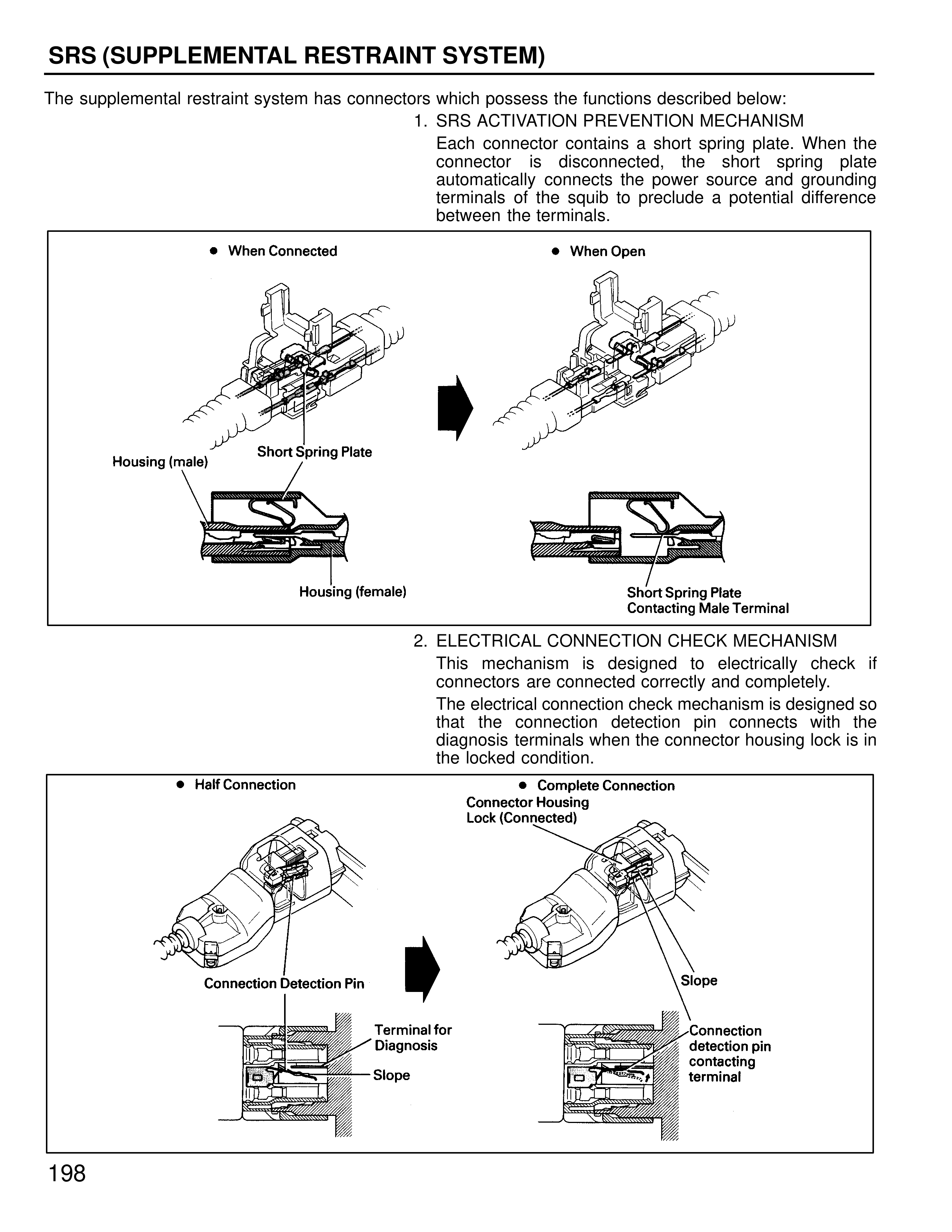
1. SRS ACTIVATION PREVENTION MECHANISM
Each connector contains a short spring plate. When the connector is disconnected, the short spring plate automatically connects the power source and grounding terminals of the squib to preclude a potential difference between the terminals.
When Connected
When Open
Housing (male)
Short Spring Plate
Housing (female)
Short Spring Plate Contacting Male Terminal
2. ELECTRICAL CONNECTION CHECK MECHANISM
This mechanism is designed to electrically check if connectors are connected correctly and completely.
The electrical connection check mechanism is designed so that the connection detection pin connects with the diagnosis terminals when the connector housing lock is in the locked condition.
Half Connection
Complete Connection
Connector Housing Lock (Connected)
Connection Detection Pin
Slope
Terminal for Diagnosis
Connection detection pin contacting terminal
Slope
198