Page text (OCR transcript)
AC–16
AIR CONDITIONING SYSTEM – TROUBLESHOOTING

PANEL DIAGNOSIS SYSTEM

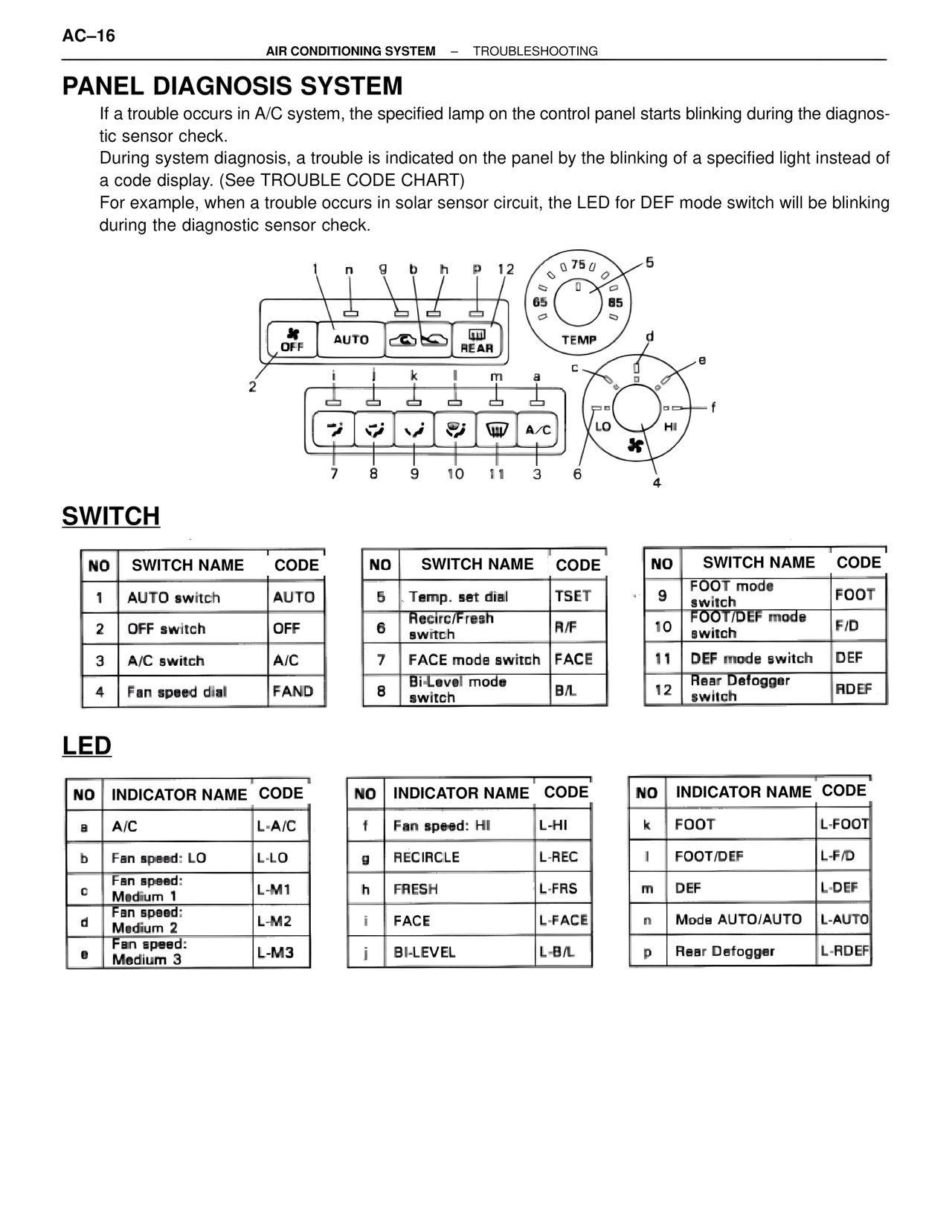
If a trouble occurs in A/C system, the specified lamp on the control panel starts blinking during the diagnostic sensor check.
During system diagnosis, a trouble is indicated on the panel by the blinking of a specified light instead of a code display. (See TROUBLE CODE CHART)
For example, when a trouble occurs in solar sensor circuit, the LED for DEF mode switch will be blinking during the diagnostic sensor check.

[DIAGRAM LABELS]
1  n  g  b  h  p  12
0  0  75  0
65  85
TEMP
d
OFF  AUTO  REAR
2
i  j  k  l  m  a
c
LO  HI
7  8  9  10  11  3  6
4
e
f
5

SWITCH

NO  SWITCH NAME  CODE
1  AUTO switch  AUTO
2  OFF switch  OFF
3  A/C switch  A/C
4  Fan speed dial  FAND

NO  SWITCH NAME  CODE
5  Temp. set dial  TSET
6  Recirc/Fresh switch  R/F
7  FACE mode switch  FACE
8  Bi-Level mode switch  B/L

NO  SWITCH NAME  CODE
9  FOOT mode switch  FOOT
10  FOOT/DEF mode switch  F/D
11  DEF mode switch  DEF
12  Rear Defogger switch  RDEF

LED

NO  INDICATOR NAME  CODE
a  A/C  L-A/C
b  Fan speed: LO  L-LO
c  Fan speed: Medium 1  L-M1
d  Fan speed: Medium 2  L-M2
e  Fan speed: Medium 3  L-M3

NO  INDICATOR NAME  CODE
f  Fan speed: HI  L-HI
g  RECIRCLE  L-REC
h  FRESH  L-FRS
i  FACE  L-FACE
j  BI-LEVEL  L-B/L

NO  INDICATOR NAME  CODE
k  FOOT  L-FOOT
l  FOOT/DEF  L-F/D
m  DEF  L-DEF
n  Mode AUTO/AUTO  L-AUTO
p  Rear Defogger  L-RDEF