100%
AC–49
AIR CONDITIONING SYSTEM – TROUBLESHOOTING
INSPECTION PROCEDURE
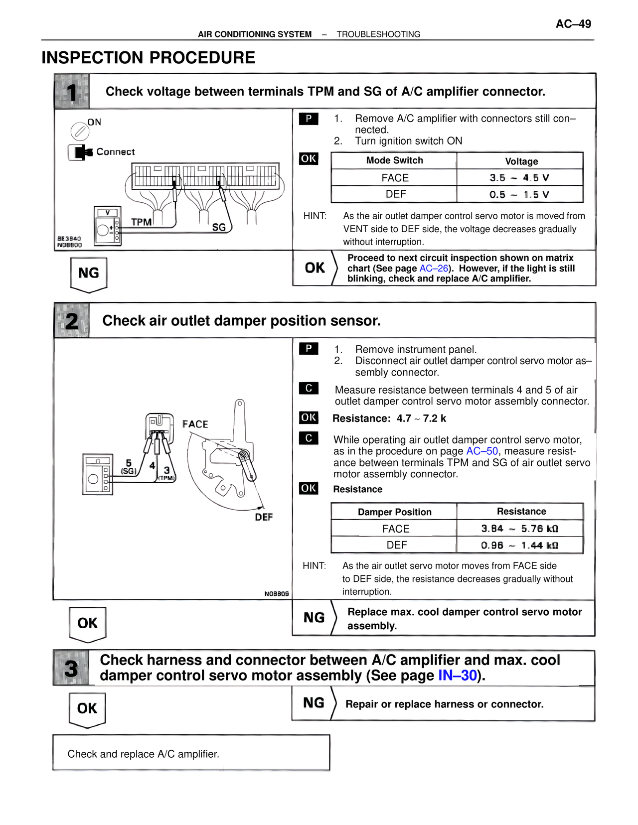
1 Check voltage between terminals TPM and SG of A/C amplifier connector.
ON
Connect
TPM SG
BE3840
N08800
P 1. Remove A/C amplifier with connectors still con–nected.
2. Turn ignition switch ON
OK
Mode Switch Voltage
FACE 3.5 ~ 4.5 V
DEF 0.5 ~ 1.5 V
HINT: As the air outlet damper control servo motor is moved from VENT side to DEF side, the voltage decreases gradually without interruption.
NG
OK Proceed to next circuit inspection shown on matrix chart (See page AC–26). However, if the light is still blinking, check and replace A/C amplifier.
2 Check air outlet damper position sensor.
FACE
5 4 3
(SG) (TPM)
DEF
N08809
P 1. Remove instrument panel.
2. Disconnect air outlet damper control servo motor assembly connector.
C Measure resistance between terminals 4 and 5 of air outlet damper control servo motor assembly connector.
OK Resistance: 4.7 ~ 7.2 k
C While operating air outlet damper control servo motor, as in the procedure on page AC–50, measure resistance between terminals TPM and SG of air outlet servo motor assembly connector.
OK Resistance
Damper Position Resistance
FACE 3.84 ~ 5.76 kΩ
DEF 0.96 ~ 1.44 kΩ
HINT: As the air outlet servo motor moves from FACE side to DEF side, the resistance decreases gradually without interruption.
OK
NG Replace max. cool damper control servo motor assembly.
3 Check harness and connector between A/C amplifier and max. cool damper control servo motor assembly (See page IN–30).
OK
NG Repair or replace harness or connector.
Check and replace A/C amplifier.