100%
AC–50
AIR CONDITIONING SYSTEM – TROUBLESHOOTING
Blinking Light HI Air Outlet Damper Control Servo Motor Circuit
CIRCUIT DESCRIPTION
This circuit turns the servo motor and changes each mode damper position by the signals from the A/C amplifier. When the AUTO switch is on, the A/C amplifier changes the mode automatically between (FACE) (BI–LEVEL) an (FOOT) according to the temperature setting.
Diagnostic Sensor Check Detecting Condition | Trouble Area
Air outlet damper position sensor value does not change even if A/C amplifier signals the air outlet damper control servo motor.
• Air outlet damper control servo motor
• Air outlet damper position sensor
• Harness or connector between A/C amplifier and air outlet damper control servo motor, air outlet damper position sensor
• A/C amplifier
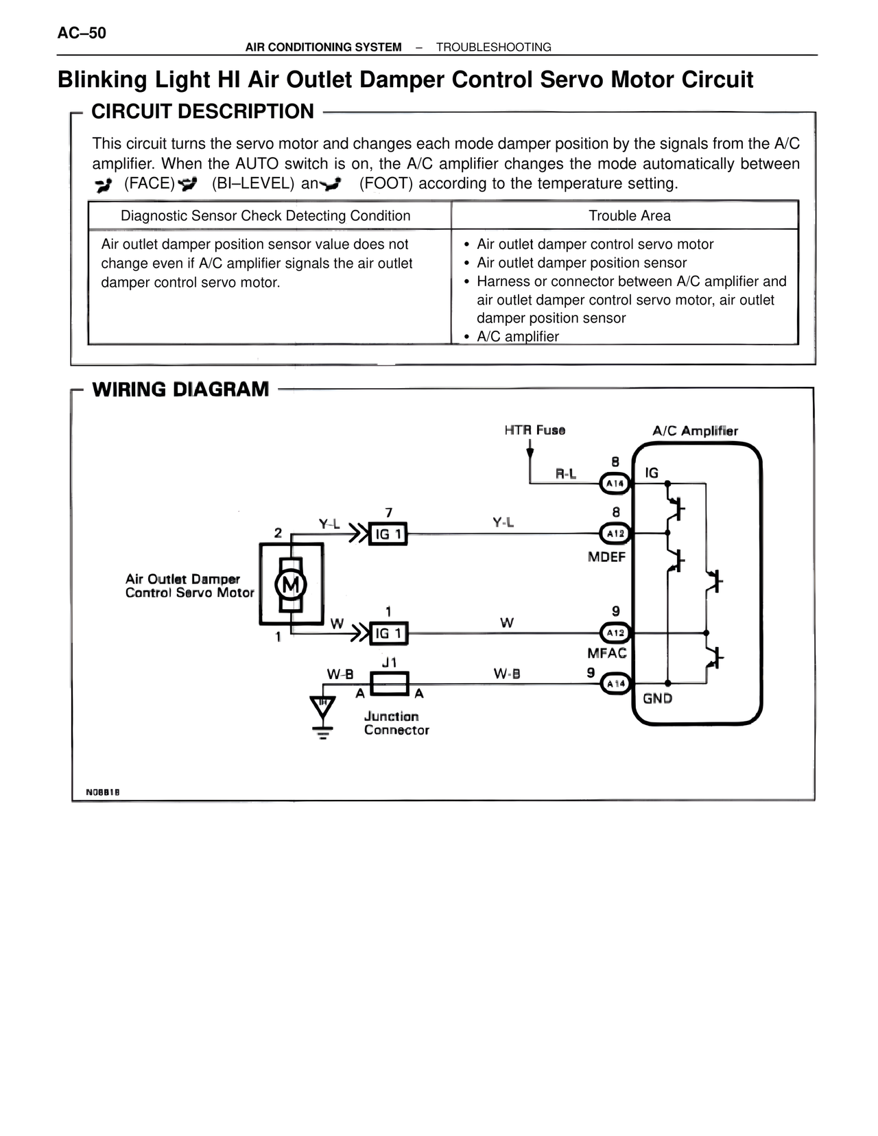
WIRING DIAGRAM
HTR Fuse
R-L
A14
IG
Y-L
2
Y-L
7
IG 1
8
A12
MDEF
Air Outlet Damper Control Servo Motor
M
W
1
W
1
IG 1
9
A12
MFAC
W-B
J1
W-B
9
A
A
A14
GND
Junction Connector
N08818