100%
AT1–10
AT340E (2JZ–GE) AUTOMATIC TRANSMISSION – OPERATION
ARRANGEMENT OF COMPONENTS
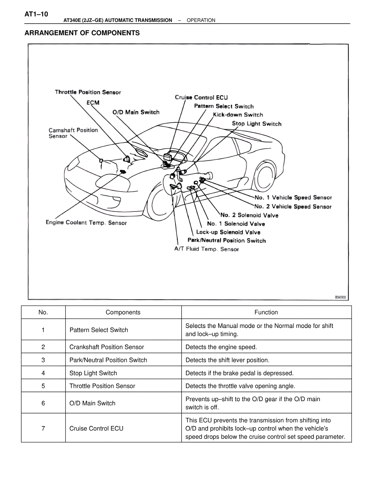
Throttle Position Sensor
ECM
O/D Main Switch
Camshaft Position
Sensor
Engine Coolant Temp. Sensor
Cruise Control ECU
Pattern Select Switch
Kick-down Switch
Stop Light Switch
No. 1 Vehicle Speed Sensor
No. 2 Vehicle Speed Sensor
No. 2 Solenoid Valve
No. 1 Solenoid Valve
Lock-up Solenoid Valve
Park/Neutral Position Switch
A/T Fluid Temp. Sensor
004300
No. | Components | Function
1 | Pattern Select Switch | Selects the Manual mode or the Normal mode for shift and lock–up timing.
2 | Crankshaft Position Sensor | Detects the engine speed.
3 | Park/Neutral Position Switch | Detects the shift lever position.
4 | Stop Light Switch | Detects if the brake pedal is depressed.
5 | Throttle Position Sensor | Detects the throttle valve opening angle.
6 | O/D Main Switch | Prevents up–shift to the O/D gear if the O/D main switch is off.
7 | Cruise Control ECU | This ECU prevents the transmission from shifting into O/D and prohibits lock–up control when the vehicle's speed drops below the cruise control set speed parameter.