100%
AT1–54
AT340E (2JZ–GE) AUTOMATIC TRANSMISSION – TROUBLESHOOTING
*1 "○" mark means "O/D OFF" indicator light blinks once every 2 seconds.
"X" mark means "O/D OFF" indicator light never blinks.
*2 "○" marks means the ECM memorizes the malfunction code if the ECM detects the diagnostic trouble code
detection condition.
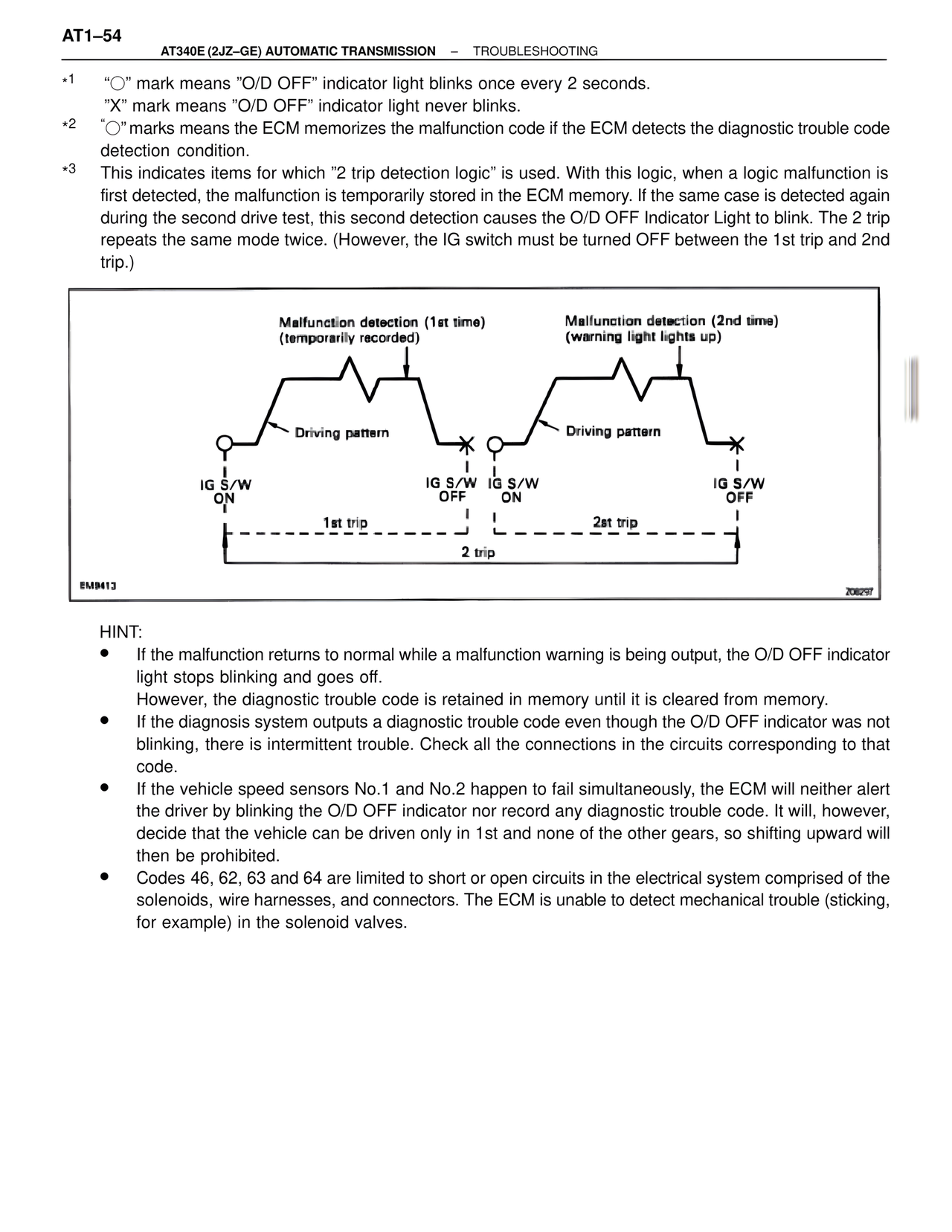
*3 This indicates items for which "2 trip detection logic" is used. With this logic, when a logic malfunction is
first detected, the malfunction is temporarily stored in the ECM memory. If the same case is detected again
during the second drive test, this second detection causes the O/D OFF Indicator Light to blink. The 2 trip
repeats the same mode twice. (However, the IG switch must be turned OFF between the 1st trip and 2nd
trip.)
Malfunction detection (1st time)
(temporarily recorded)
Driving pattern
IG S/W
ON
IG S/W
OFF
IG S/W
ON
1st trip
Malfunction detection (2nd time)
(warning light lights up)
Driving pattern
IG S/W
OFF
2st trip
2 trip
EM9413 206297
HINT:
• If the malfunction returns to normal while a malfunction warning is being output, the O/D OFF indicator
light stops blinking and goes off.
However, the diagnostic trouble code is retained in memory until it is cleared from memory.
• If the diagnosis system outputs a diagnostic trouble code even though the O/D OFF indicator was not
blinking, there is intermittent trouble. Check all the connections in the circuits corresponding to that
code.
• If the vehicle speed sensors No.1 and No.2 happen to fail simultaneously, the ECM will neither alert
the driver by blinking the O/D OFF indicator nor record any diagnostic trouble code. It will, however,
decide that the vehicle can be driven only in 1st and none of the other gears, so shifting upward will
then be prohibited.
• Codes 46, 62, 63 and 64 are limited to short or open circuits in the electrical system comprised of the
solenoids, wire harnesses, and connectors. The ECM is unable to detect mechanical trouble (sticking,
for example) in the solenoid valves.