100%
AT2–100
A340E (2JZ—GTE) AUTOMATIC TRANSMISSION – TROUBLESHOOTING
INSPECTION PROCEDURE
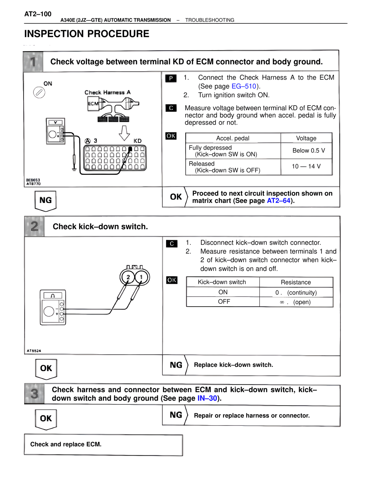
1 Check voltage between terminal KD of ECM connector and body ground.
ON
Check Harness A
ECM
@ 3 KD
BE8653
AT8770
P 1. Connect the Check Harness A to the ECM (See page EG–510).
2. Turn ignition switch ON.
C Measure voltage between terminal KD of ECM connector and body ground when accel. pedal is fully depressed or not.
OK
Accel. pedal Voltage
Fully depressed
(Kick–down SW is ON) Below 0.5 V
Released
(Kick–down SW is OFF) 10 — 14 V
NG
OK Proceed to next circuit inspection shown on matrix chart (See page AT2–64).
2 Check kick–down switch.
2 1
AT8524
C 1. Disconnect kick–down switch connector.
2. Measure resistance between terminals 1 and 2 of kick–down switch connector when kick–down switch is on and off.
OK
Kick–down switch Resistance
ON 0 . (continuity)
OFF ∞ . (open)
OK
NG Replace kick–down switch.
3 Check harness and connector between ECM and kick–down switch, kick–down switch and body ground (See page IN–30).
OK
NG Repair or replace harness or connector.
Check and replace ECM.