100%
BR–143
BRAKE SYSTEM – TRACTION CONTROL SYSTEM (TRAC)
INSPECTION PROCEDURE
1 Check battery positive voltage.
OK Voltage: 10 – 14 V
OK NG Check and repair the charging system.
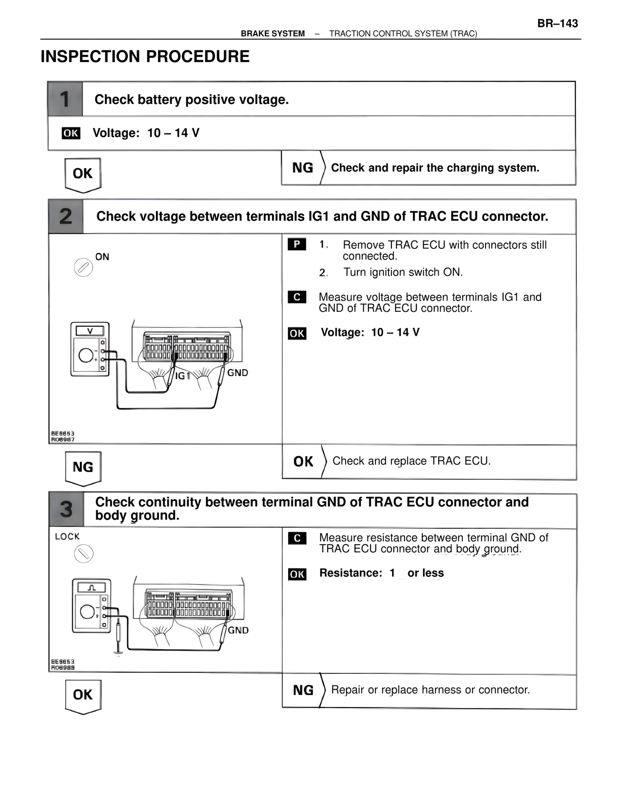
2 Check voltage between terminals IG1 and GND of TRAC ECU connector.
ON
P 1. Remove TRAC ECU with connectors still connected.
2. Turn ignition switch ON.
C Measure voltage between terminals IG1 and GND of TRAC ECU connector.
OK Voltage: 10 – 14 V
IG1 GND
BE8653
R06987
NG OK Check and replace TRAC ECU.
3 Check continuity between terminal GND of TRAC ECU connector and body ground.
LOCK
C Measure resistance between terminal GND of TRAC ECU connector and body ground.
OK Resistance: 1 or less
GND
BE8653
R06988
OK NG Repair or replace harness or connector.