100%
BR–158
BRAKE SYSTEM – TRACTION CONTROL SYSTEM (TRAC)
INSPECTION PROCEDURE
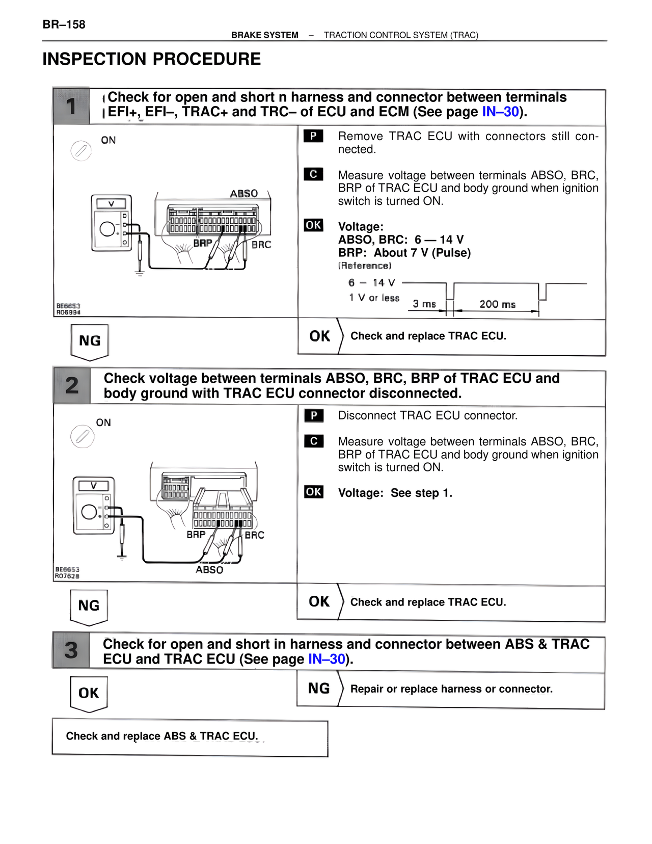
1 Check for open and short n harness and connector between terminals
EFI+, EFI–, TRAC+ and TRC– of ECU and ECM (See page IN–30).
ON
ABSO
BRP BRC
BE6653
R06984
P Remove TRAC ECU with connectors still connected.
C Measure voltage between terminals ABSO, BRC, BRP of TRAC ECU and body ground when ignition switch is turned ON.
OK Voltage:
ABSO, BRC: 6 — 14 V
BRP: About 7 V (Pulse)
(Reference)
6 – 14 V
1 V or less
3 ms 200 ms
NG OK Check and replace TRAC ECU.
2 Check voltage between terminals ABSO, BRC, BRP of TRAC ECU and
body ground with TRAC ECU connector disconnected.
ON
BRP BRC
BE6653
RO7628
ABSO
P Disconnect TRAC ECU connector.
C Measure voltage between terminals ABSO, BRC, BRP of TRAC ECU and body ground when ignition switch is turned ON.
OK Voltage: See step 1.
NG OK Check and replace TRAC ECU.
3 Check for open and short in harness and connector between ABS & TRAC
ECU and TRAC ECU (See page IN–30).
OK NG Repair or replace harness or connector.
Check and replace ABS & TRAC ECU.