Page text (OCR transcript)
BR–44
BRAKE SYSTEM – ANTI–LOCK BRAKE SYSTEM (ABS)

ABS ACTUATOR REMOVAL

Installation is in the reverse order of removal.
AFTER INSTALLATION, BLEED BRAKE SYSTEM (See page BR–7) AND BLEED TRAC SYSTEM (See page BR–9)

1. REMOVE CRUISE CONTROL ACTUATOR
Remove the 3 bolts and cruise control actuator.
Torque:
Cruise control actuator X Body
13 N·m (130 kgf·cm, 9 ft·lbf)
Cruise control actuator X ABS actuator X Body
19 N·m (195 kgf·cm, 14 ft·lbf)

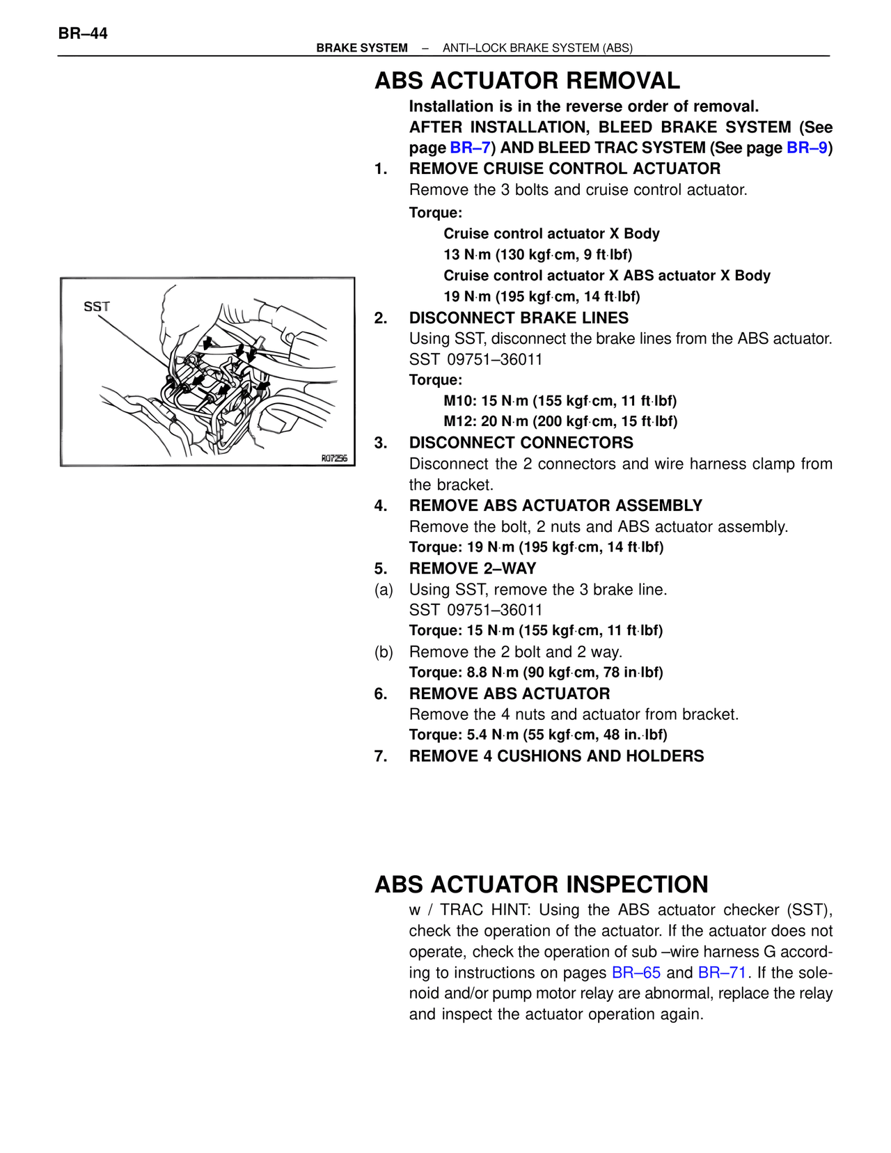
2. DISCONNECT BRAKE LINES
Using SST, disconnect the brake lines from the ABS actuator.
SST 09751–36011
Torque:
M10: 15 N·m (155 kgf·cm, 11 ft·lbf)
M12: 20 N·m (200 kgf·cm, 15 ft·lbf)

3. DISCONNECT CONNECTORS
Disconnect the 2 connectors and wire harness clamp from the bracket.

4. REMOVE ABS ACTUATOR ASSEMBLY
Remove the bolt, 2 nuts and ABS actuator assembly.
Torque: 19 N·m (195 kgf·cm, 14 ft·lbf)

5. REMOVE 2–WAY
(a) Using SST, remove the 3 brake line.
SST 09751–36011
Torque: 15 N·m (155 kgf·cm, 11 ft·lbf)
(b) Remove the 2 bolt and 2 way.
Torque: 8.8 N·m (90 kgf·cm, 78 in·lbf)

6. REMOVE ABS ACTUATOR
Remove the 4 nuts and actuator from bracket.
Torque: 5.4 N·m (55 kgf·cm, 48 in.·lbf)

7. REMOVE 4 CUSHIONS AND HOLDERS

SST
R07256

ABS ACTUATOR INSPECTION

w / TRAC HINT: Using the ABS actuator checker (SST), check the operation of the actuator. If the actuator does not operate, check the operation of sub –wire harness G according to instructions on pages BR–65 and BR–71. If the solenoid and/or pump motor relay are abnormal, replace the relay and inspect the actuator operation again.