100%
BR–86
BRAKE SYSTEM – ANTI–LOCK BRAKE SYSTEM (ABS)
DTC 25 27 TRAC Actuator Solenoid Circuit
CIRCUIT DESCRIPTION
The TRAC actuator solenoid operates in accordance with signals from the ECU and raises the fluid pressure
in and releases it from the brake cylinders.
DTC No. | Diagnostic Trouble Code Detecting Condition | Trouble area
25
Conditions (1) and (2) continue for 0.05 sec.
or more:
(1) TRAC solenoid relay terminal (TSR)
voltage: Battery positive voltage
(2) Voltage oS & TRAC ECU terminal AB
SMC: 0 V
TRAC actuator
Open or short in SMC circuit
ECU
27
Conditions (1) and (2) continue for 0.05 sec.
or more:
(1) TRAC solenoid relay terminal (TSR)
voltage: Battery positive voltage
(2) Voltage of ABS & TRAC ECU terminal
SRC: 0V
TRAC actuator
Open or short in SRC circuit
ECU
Fail safe function: If trouble occurs in this solenoid circuit, the ECU cuts off current to the ABS and TRAC solenoid
relays and prohibits ABS and TRAC control.
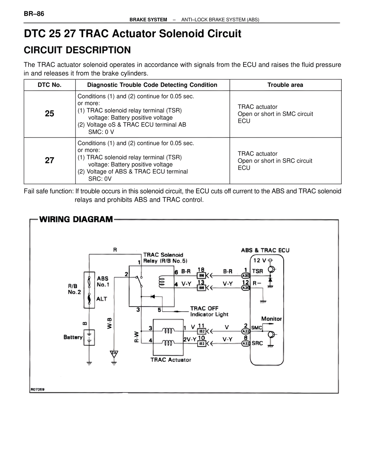
WIRING DIAGRAM
R
TRAC Solenoid
1 Relay (R/B No.5)
6 B-R 18 B-R 1 TSR
2 IB6
ABS 4 V-Y 13 V-Y 12 R-
No.1 IB6 A20
R/B
No.2
ALT
3 5
TRAC OFF
Indicator Light Monitor
m
W-B 3 1 V 11 V 2 SMC
Battery R-W IB2 A23
4 2V-Y 10 V-Y 8 SRC
IB2 A23
TRAC Actuator
ABS & TRAC ECU
12 V
RO7069