100%
BR–96
BRAKE SYSTEM – ANTI–LOCK BRAKE SYSTEM (ABS)
INSPECTION PROCEDURE.
1 Check for open and short in harness and connector between sensor and ECU (See page IN–30).
OK
NG Repair or replace harness or connector.
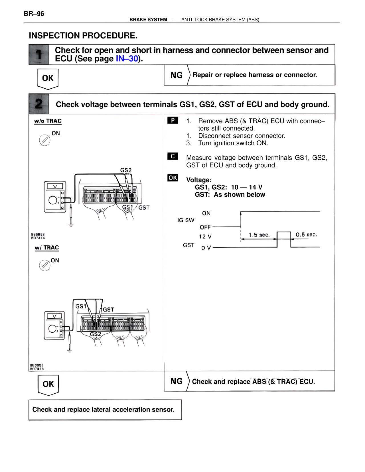
2 Check voltage between terminals GS1, GS2, GST of ECU and body ground.
w/o TRAC
ON
GS2
GS1 GST
BE6653
RO7414
w/ TRAC
ON
GS1 GST
GS2
BE6653
RO7415
P 1. Remove ABS (& TRAC) ECU with connectors still connected.
1. Disconnect sensor connector.
3. Turn ignition switch ON.
C Measure voltage between terminals GS1, GS2, GST of ECU and body ground.
OK Voltage:
GS1, GS2: 10 — 14 V
GST: As shown below
IG SW ON
OFF
12 V 1.5 sec. 0.5 sec.
GST 0 V
OK
NG Check and replace ABS (& TRAC) ECU.
Check and replace lateral acceleration sensor.