100%
BE–130
BODY ELECTRICAL SYSTEM – THEFT DETERRENT AND DOOR LOCK CONTROL SYSTEM
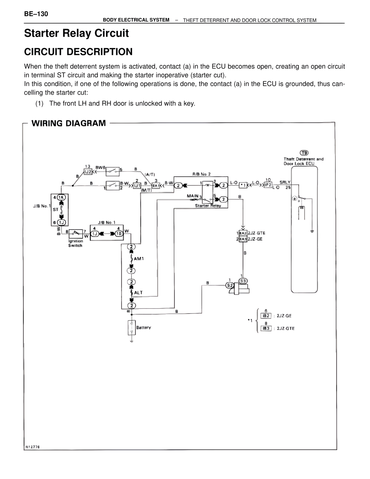
Starter Relay Circuit
CIRCUIT DESCRIPTION
When the theft deterrent system is activated, contact (a) in the ECU becomes open, creating an open circuit in terminal ST circuit and making the starter inoperative (starter cut).
In this condition, if one of the following operations is done, the contact (a) in the ECU is grounded, thus cancelling the starter cut:
(1) The front LH and RH door is unlocked with a key.
WIRING DIAGRAM
T9
Theft Deterrent and
Door Lock ECU
13
LJ2
BW6
B
B
(A/T)
R/B No. 2
B
B-W
B-W
L-O
L-O
10
IF2
SRLY
25
EA1
(M/T)
2
2
1
1
MAIN 3
2
B
Starter Relay
8
4
1K
J/B No. 1
ST
6
1J
B-W
8
7
W
4
4
1J
1B
W
J/B No. 1
1
EA2 2JZ-GTE
2
EA3 2JZ-GE
Ignition
Switch
2
AM1
2
2
ALT
2
B
S2
1
S3
B
∞
B
6
IB2 : 2JZ-GE
*1
8
IB3 : 2JZ-GTE
Battery
N12776