100%
BE–129
BODY ELECTRICAL SYSTEM – THEFT DETERRENT AND DOOR LOCK CONTROL SYSTEM
INSPECTION PROCEDURE
1 Check indicator light
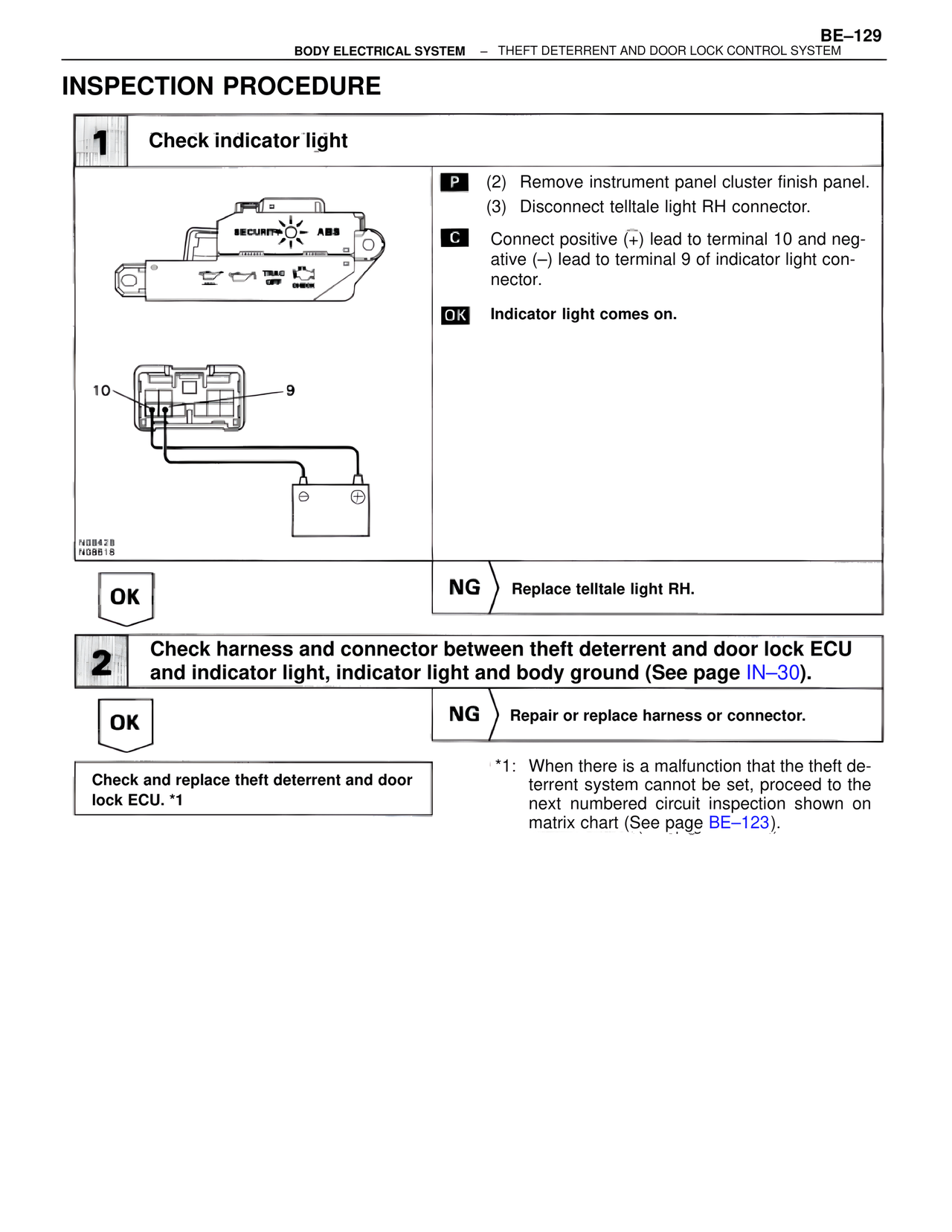
P (2) Remove instrument panel cluster finish panel.
(3) Disconnect telltale light RH connector.
C Connect positive (+) lead to terminal 10 and negative (–) lead to terminal 9 of indicator light connector.
OK Indicator light comes on.
10 9
N08428
N08618
OK NG > Replace telltale light RH.
2 Check harness and connector between theft deterrent and door lock ECU and indicator light, indicator light and body ground (See page IN–30).
OK NG > Repair or replace harness or connector.
Check and replace theft deterrent and door lock ECU. *1
*1: When there is a malfunction that the theft deterrent system cannot be set, proceed to the next numbered circuit inspection shown on matrix chart (See page BE–123).