100%
BE–137
BODY ELECTRICAL SYSTEM – THEFT DETERRENT AND DOOR LOCK CONTROL SYSTEM
INSPECTION PROCEDURE
HINT: The flow chart below is based on the premise that the headlights light up normally whenever the light con–
trol switch is operated. If headlight operation is not normal when the light control switch is operated, pro–
ceed to troubleshooting on page BE–11.
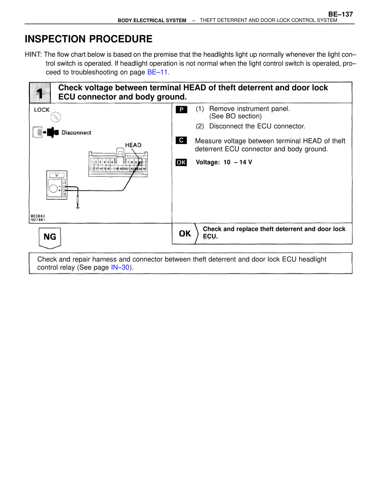
1 Check voltage between terminal HEAD of theft deterrent and door lock ECU connector and body ground.
LOCK
Disconnect
HEAD
BE3B43
N074B1
P (1) Remove instrument panel.
(See BO section)
(2) Disconnect the ECU connector.
C Measure voltage between terminal HEAD of theft deterrent ECU connector and body ground.
OK Voltage: 10 – 14 V
NG
OK Check and replace theft deterrent and door lock ECU.
Check and repair harness and connector between theft deterrent and door lock ECU headlight control relay (See page IN–30).