100%
BE–138
BODY ELECTRICAL SYSTEM – THEFT DETERRENT AND DOOR LOCK CONTROL SYSTEM
Taillight Control Relay Circuit
CIRCUIT DESCRIPTION
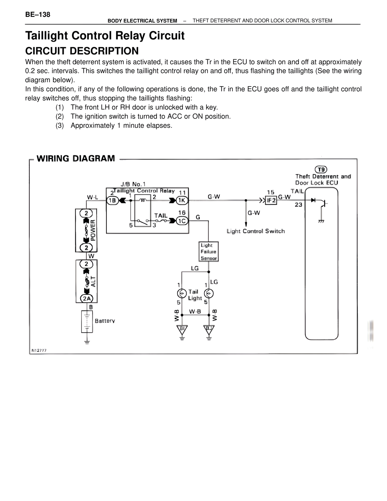
When the theft deterrent system is activated, it causes the Tr in the ECU to switch on and off at approximately 0.2 sec. intervals. This switches the taillight control relay on and off, thus flashing the taillights (See the wiring diagram below).
In this condition, if any of the following operations is done, the Tr in the ECU goes off and the taillight control relay switches off, thus stopping the taillights flashing:
(1) The front LH or RH door is unlocked with a key.
(2) The ignition switch is turned to ACC or ON position.
(3) Approximately 1 minute elapses.
WIRING DIAGRAM
T9
Theft Deterrent and
Door Lock ECU
J/B No.1
2 Taillight Control Relay
1 2 11
W-L
1B
G-W
15 TAIL
IF2 G-W
23
TAIL 16 G
5 3 1C
G-W
Light Control Switch
Light
Failure
Sensor
LG
1 LG
Tail
Light
5 5
W-B W-B
W-B
2
POWER
2
W
2
ALT
2A
B
Battery
N12777