Page text (OCR transcript)
BE-139
BODY ELECTRICAL SYSTEM – THEFT DETERRENT AND DOOR LOCK CONTROL SYSTEM

INSPECTION PROCEDURE

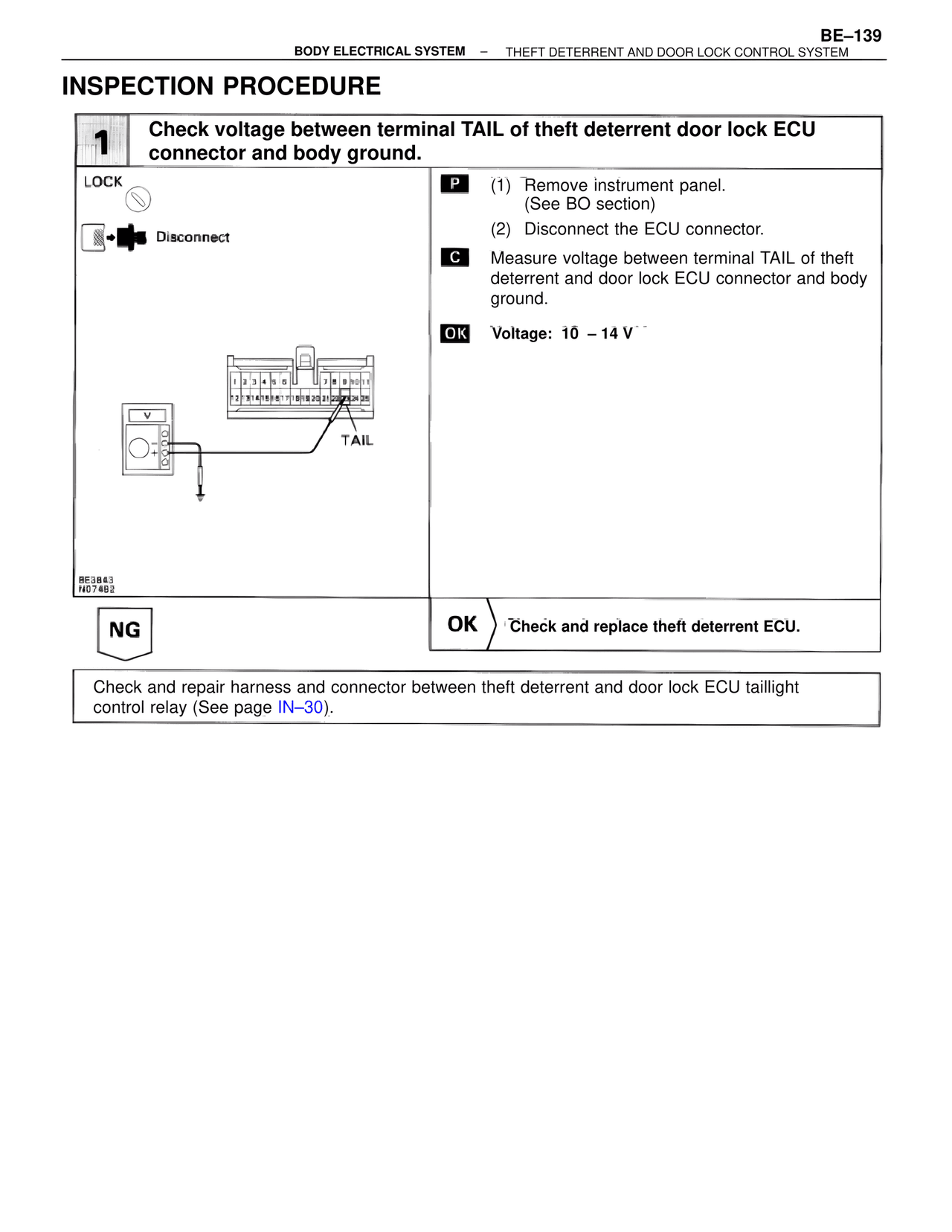
1  Check voltage between terminal TAIL of theft deterrent door lock ECU connector and body ground.

LOCK

Disconnect

P  (1) Remove instrument panel.
      (See BO section)
   (2) Disconnect the ECU connector.

C  Measure voltage between terminal TAIL of theft deterrent and door lock ECU connector and body ground.

OK  Voltage: 10 – 14 V

TAIL

BE3843
N07482

NG                    OK  Check and replace theft deterrent ECU.

Check and repair harness and connector between theft deterrent and door lock ECU taillight control relay (See page IN–30).