Page text (OCR transcript)
BE-143
BODY ELECTRICAL SYSTEM – THEFT DETERRENT AND DOOR LOCK CONTROL SYSTEM

INSPECTION PROCEDURE

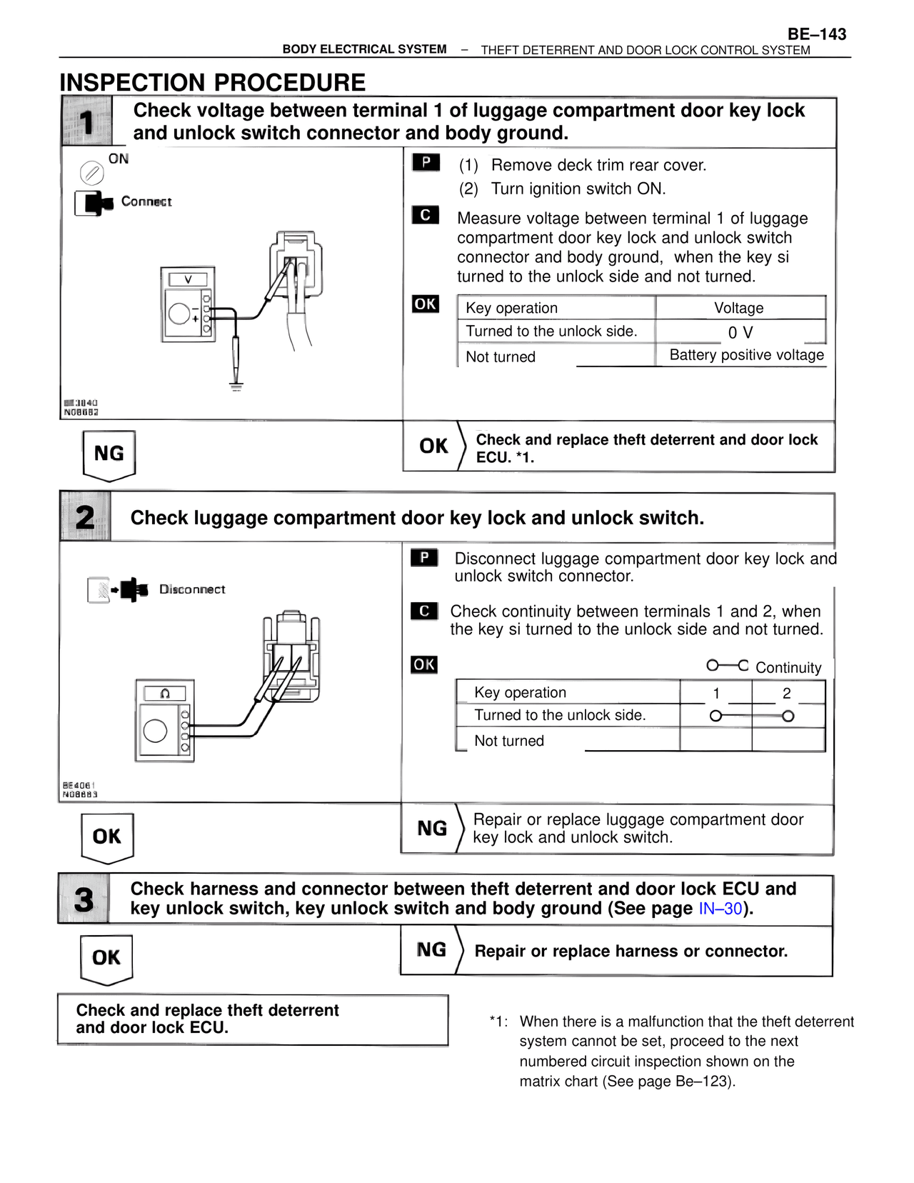
1 Check voltage between terminal 1 of luggage compartment door key lock and unlock switch connector and body ground.

ON
Connect

P (1) Remove deck trim rear cover.
(2) Turn ignition switch ON.

C Measure voltage between terminal 1 of luggage compartment door key lock and unlock switch connector and body ground, when the key si turned to the unlock side and not turned.

OK
Key operation          Voltage
Turned to the unlock side.     0 V
Not turned          Battery positive voltage

BE3840
N08682

NG          OK Check and replace theft deterrent and door lock ECU. *1.

2 Check luggage compartment door key lock and unlock switch.

Disconnect

P Disconnect luggage compartment door key lock and unlock switch connector.

C Check continuity between terminals 1 and 2, when the key si turned to the unlock side and not turned.

OK                    O—C Continuity
Key operation          1     2
Turned to the unlock side.    O——O
Not turned

BE4061
N08683

OK          NG Repair or replace luggage compartment door key lock and unlock switch.

3 Check harness and connector between theft deterrent and door lock ECU and key unlock switch, key unlock switch and body ground (See page IN-30).

OK          NG Repair or replace harness or connector.

Check and replace theft deterrent and door lock ECU.

*1: When there is a malfunction that the theft deterrent system cannot be set, proceed to the next numbered circuit inspection shown on the matrix chart (See page Be-123).