100%
BE–156
BODY ELECTRICAL SYSTEM – THEFT DETERRENT AND DOOR LOCK CONTROL SYSTEM
Door Lock Control Switch Circuit
CIRCUIT DESCRIPTION
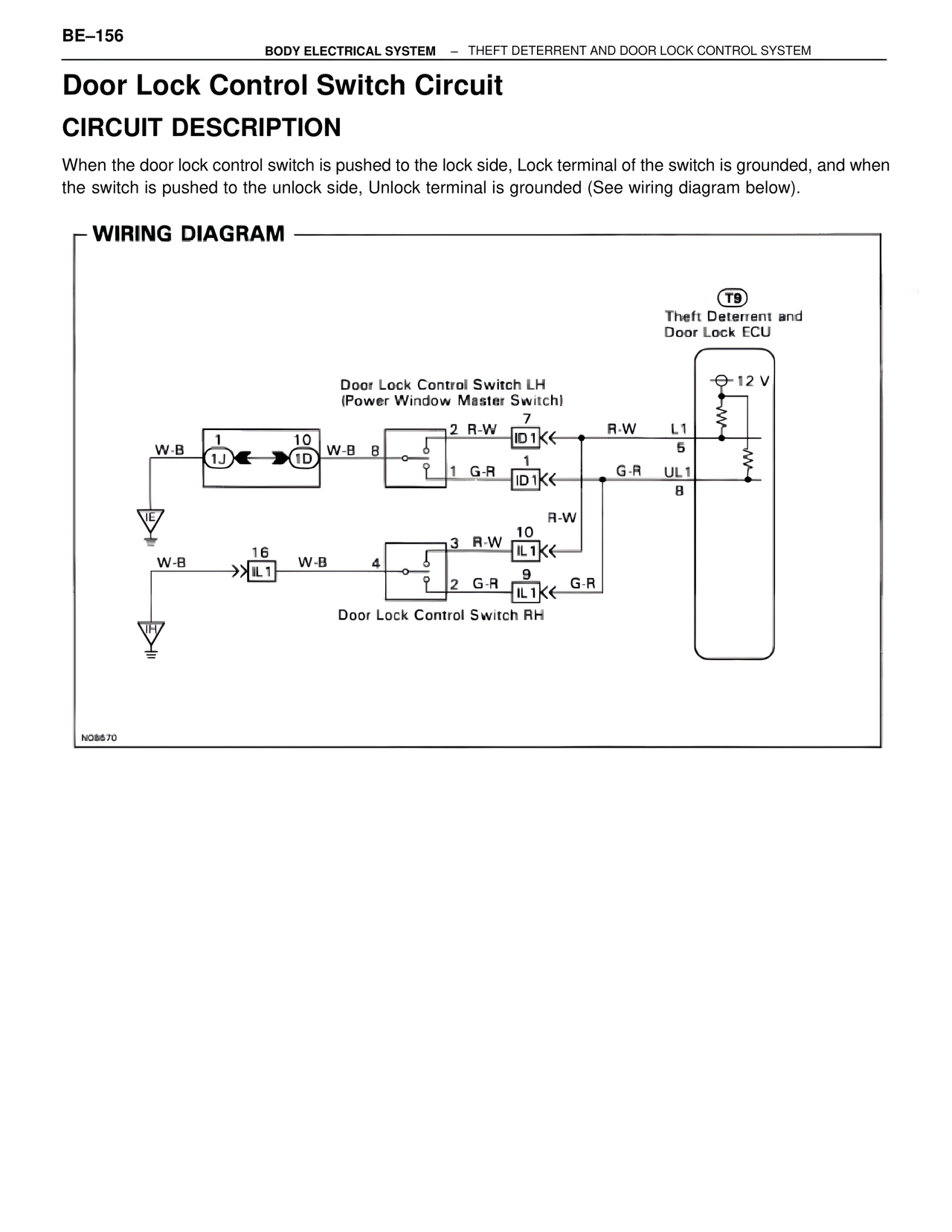
When the door lock control switch is pushed to the lock side, Lock terminal of the switch is grounded, and when the switch is pushed to the unlock side, Unlock terminal is grounded (See wiring diagram below).
WIRING DIAGRAM
T9
Theft Deterrent and
Door Lock ECU
12 V
Door Lock Control Switch LH
(Power Window Master Switch)
2 R-W
7
ID1 R-W L1
5
1 G-R
1
ID1 G-R UL1
8
W-B
1
10
1J 1D W-B 8
IE
R-W
3 R-W
10
IL1
W-B 16
2 G-R
9
IL1 W-B 4
G-R
IH
Door Lock Control Switch RH
NO8670