100%
BE–158
BODY ELECTRICAL SYSTEM – THEFT DETERRENT AND DOOR LOCK CONTROL SYSTEM
Door Key Lock and Unlock Switch Circuit
CIRCUIT DESCRIPTION
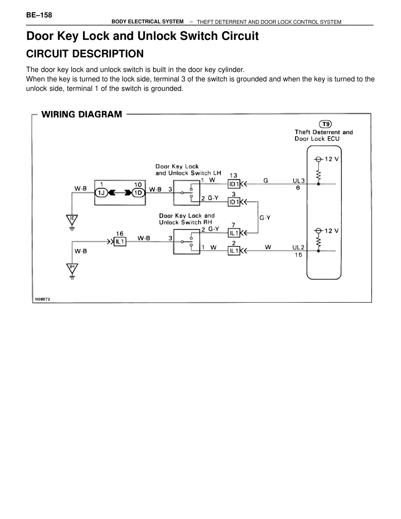
The door key lock and unlock switch is built in the door key cylinder.
When the key is turned to the lock side, terminal 3 of the switch is grounded and when the key is turned to the unlock side, terminal 1 of the switch is grounded.
WIRING DIAGRAM
T9
Theft Deterrent and
Door Lock ECU
12 V
Door Key Lock
and Unlock Switch LH
1 W
13
ID1<< G UL3
6
W-B 1 10
W-B 3
1J 1D
3
ID1<<
2 G-Y
Door Key Lock and
Unlock Switch RH
G-Y
12 V
16
2 G-Y 7
IL1<<
IL1 W-B 3
1 W 2
W-B IL1<< W UL2
15
N98672