100%
BE-159
BODY ELECTRICAL SYSTEM – THEFT DETERRENT AND DOOR LOCK CONTROL SYSTEM
INSPECTION PROCEDURE
1 Check door key lock and unlock switch.
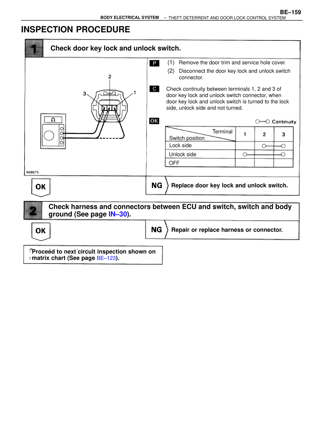
P (1) Remove the door trim and service hole cover.
(2) Disconnect the door key lock and unlock switch connector.
C Check continuity between terminals 1, 2 and 3 of door key lock and unlock switch connector, when door key lock and unlock switch is turned to the lock side, unlock side and not turned.
OK O—O Continuity
Terminal 1 2 3
Switch position
Lock side O——O
Unlock side O——O
OFF
N08675
OK NG Replace door key lock and unlock switch.
2 Check harness and connectors between ECU and switch, switch and body ground (See page IN–30).
OK NG Repair or replace harness or connector.
Proceed to next circuit inspection shown on matrix chart (See page BE–123).