100%
BE-161
BODY ELECTRICAL SYSTEM – THEFT DETERRENT AND DOOR LOCK CONTROL SYSTEM
INSPECTION PROCEDURE
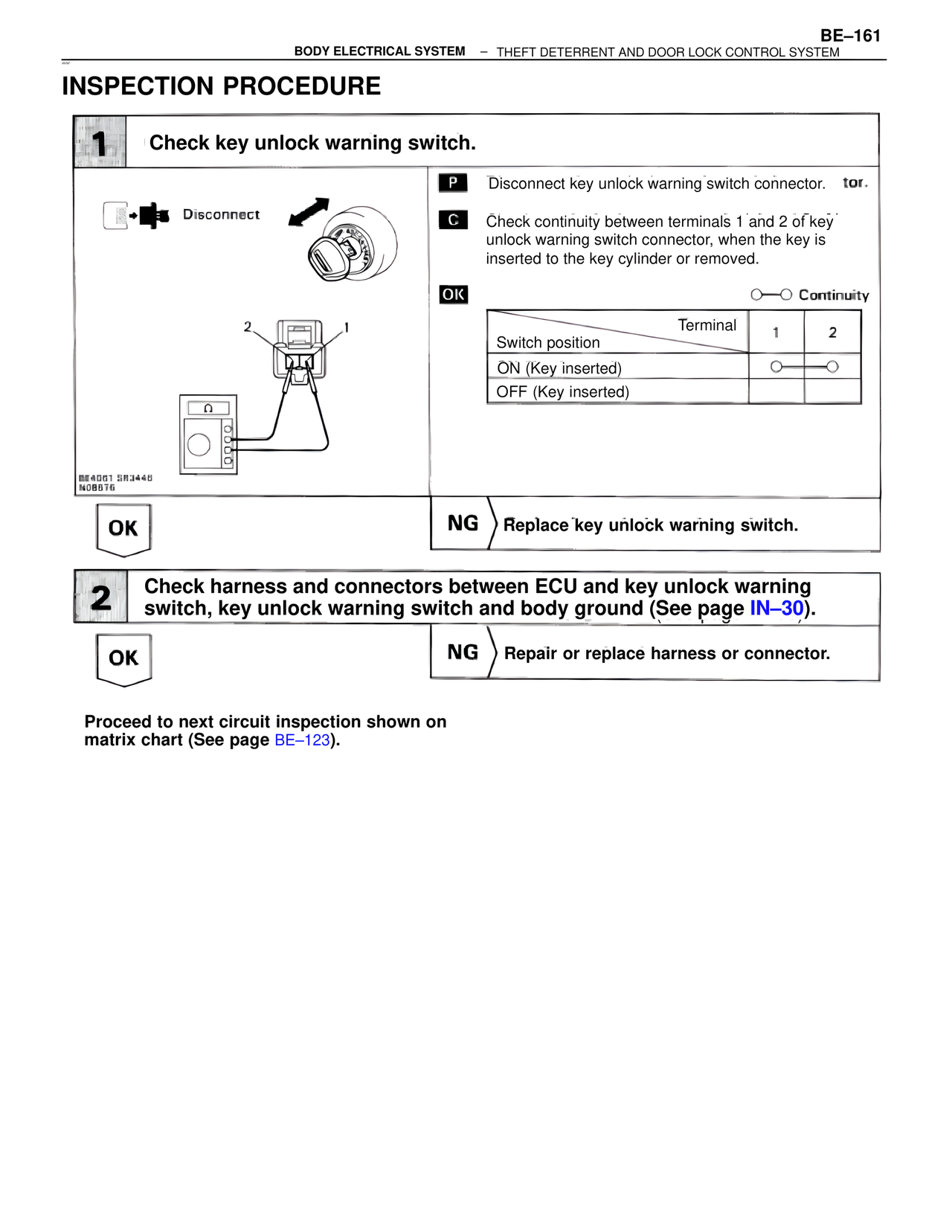
1 Check key unlock warning switch.
Disconnect
P Disconnect key unlock warning switch connector. tor.
C Check continuity between terminals 1 and 2 of key unlock warning switch connector, when the key is inserted to the key cylinder or removed.
OK ○——○ Continuity
Terminal 1 2
Switch position
ON (Key inserted) ○——○
OFF (Key inserted)
BE4001 SR3448
N08076
OK NG > Replace key unlock warning switch.
2 Check harness and connectors between ECU and key unlock warning switch, key unlock warning switch and body ground (See page IN–30).
OK NG > Repair or replace harness or connector.
Proceed to next circuit inspection shown on matrix chart (See page BE–123).