Page text (OCR transcript)
BODY ELECTRICAL SYSTEM  –  CRUISE CONTROL SYSTEM

BE–165

DIAGNOSIS SYSTEM

INDICATOR CHECK

1.    Turn the ignition switch to ON.
2.    Check that the CRUISE MAIN indicator light comes on when
the cruise control main switch is turned ON, and that the
indicator light goes off when the main switch is turned OFF.
HINT: If the indicator check result is not normal, proceed to
troubleshooting (See page BE–43 for the combination meter
section.)

DIAGNOSTIC TROUBLE CODE CHECK

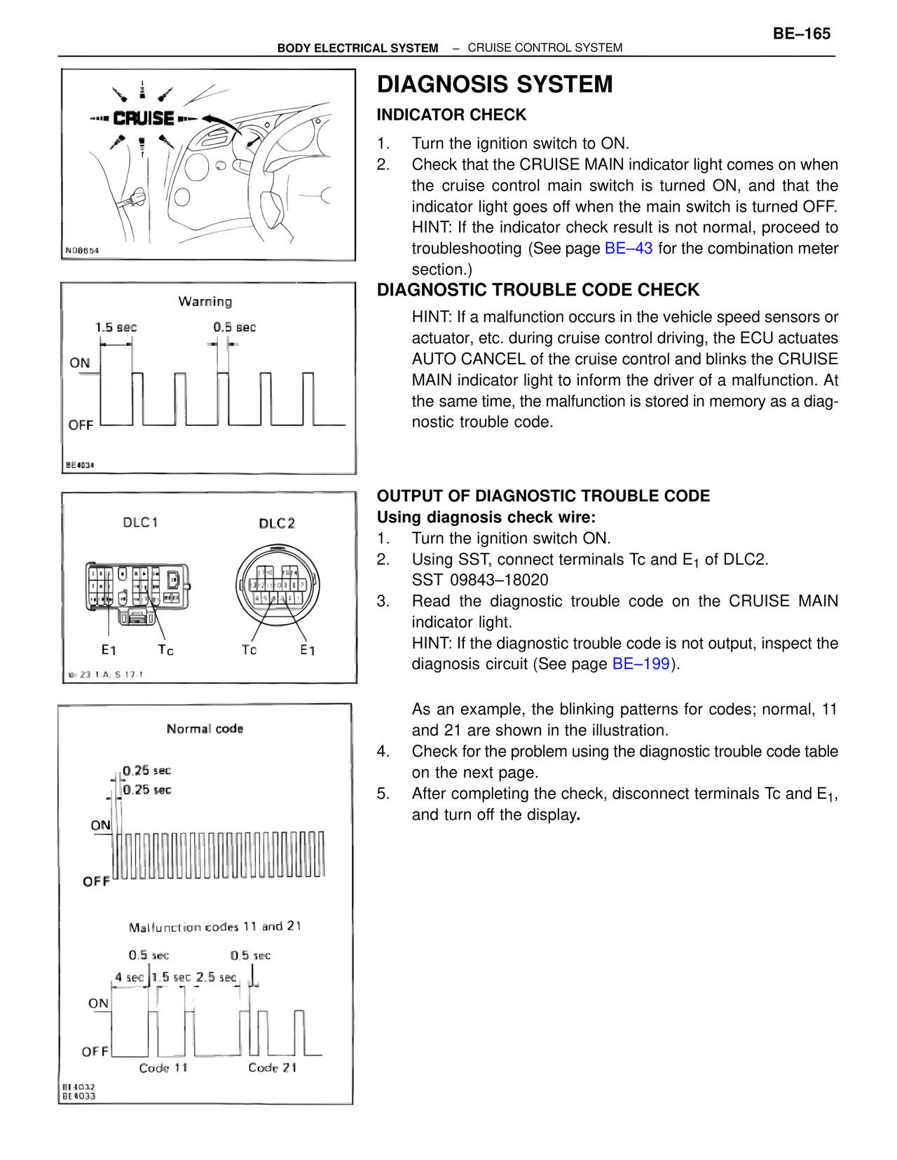
HINT: If a malfunction occurs in the vehicle speed sensors or
actuator, etc. during cruise control driving, the ECU actuates
AUTO CANCEL of the cruise control and blinks the CRUISE
MAIN indicator light to inform the driver of a malfunction. At
the same time, the malfunction is stored in memory as a diag-
nostic trouble code.

OUTPUT OF DIAGNOSTIC TROUBLE CODE
Using diagnosis check wire:
1.    Turn the ignition switch ON.
2.    Using SST, connect terminals Tc and E1 of DLC2.
SST 09843–18020
3.    Read the diagnostic trouble code on the CRUISE MAIN
indicator light.
HINT: If the diagnostic trouble code is not output, inspect the
diagnosis circuit (See page BE–199).

As an example, the blinking patterns for codes; normal, 11
and 21 are shown in the illustration.
4.    Check for the problem using the diagnostic trouble code table
on the next page.
5.    After completing the check, disconnect terminals Tc and E1,
and turn off the display.

Warning
1.5 sec          0.5 sec
ON
OFF
BE4034

DLC1                    DLC2
E1      Tc              Tc      E1
k=-23-1 A, S-17-1

Normal code
0.25 sec
0.25 sec
ON
OFF

Malfunction codes 11 and 21
0.5 sec          0.5 sec
4 sec  1.5 sec  2.5 sec
ON
OFF
Code 11          Code 21
BE4032
BE4033