100%
BODY ELECTRICAL SYSTEM – HEADLIGHT AND TAILLIGHT SYSTEM
BE–17
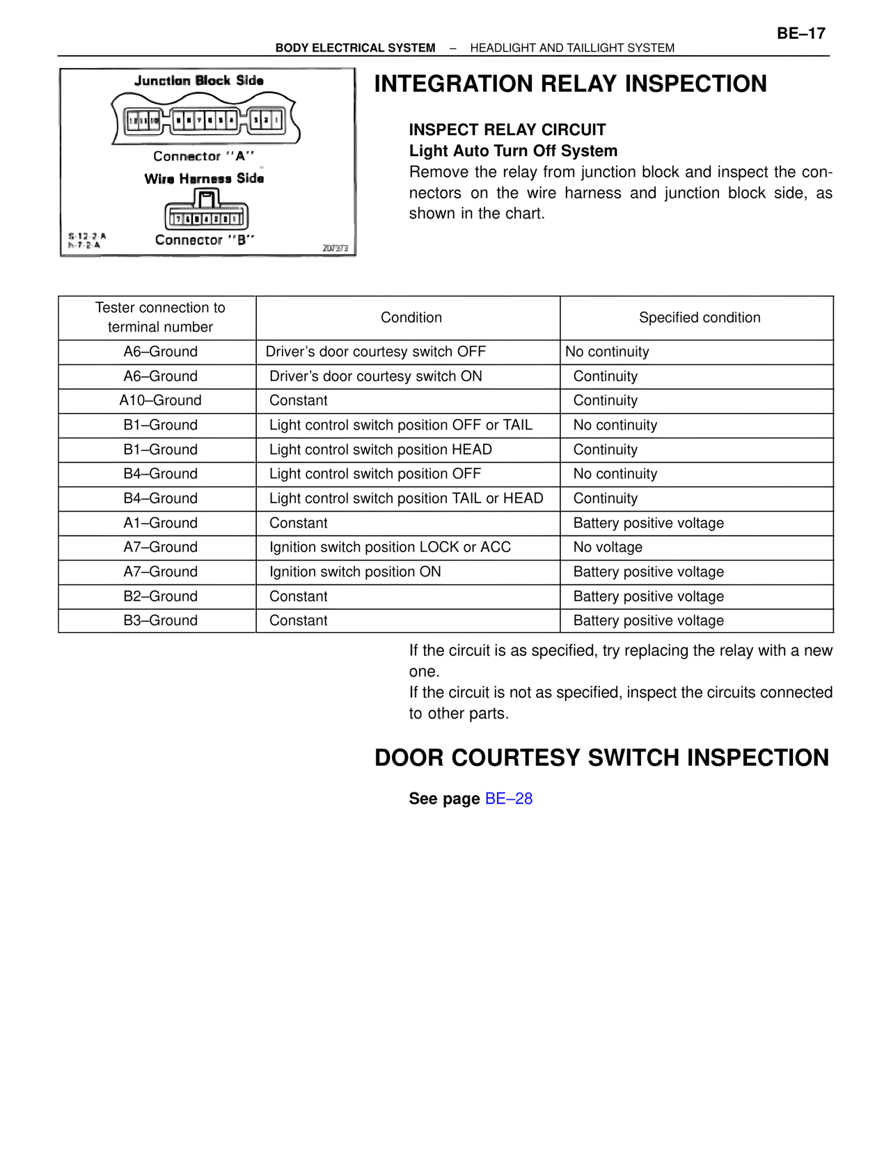
Junction Block Side
Connector "A"
Wire Harness Side
Connector "B"
6-12-2-A
h-7-2-A
200373
INTEGRATION RELAY INSPECTION
INSPECT RELAY CIRCUIT
Light Auto Turn Off System
Remove the relay from junction block and inspect the connectors on the wire harness and junction block side, as shown in the chart.
Tester connection to terminal number | Condition | Specified condition
A6–Ground | Driver's door courtesy switch OFF | No continuity
A6–Ground | Driver's door courtesy switch ON | Continuity
A10–Ground | Constant | Continuity
B1–Ground | Light control switch position OFF or TAIL | No continuity
B1–Ground | Light control switch position HEAD | Continuity
B4–Ground | Light control switch position OFF | No continuity
B4–Ground | Light control switch position TAIL or HEAD | Continuity
A1–Ground | Constant | Battery positive voltage
A7–Ground | Ignition switch position LOCK or ACC | No voltage
A7–Ground | Ignition switch position ON | Battery positive voltage
B2–Ground | Constant | Battery positive voltage
B3–Ground | Constant | Battery positive voltage
If the circuit is as specified, try replacing the relay with a new one.
If the circuit is not as specified, inspect the circuits connected to other parts.
DOOR COURTESY SWITCH INSPECTION
See page BE–28