100%
BE–174
BODY ELECTRICAL SYSTEM – CRUISE CONTROL SYSTEM
INSPECTION PROCEDURE
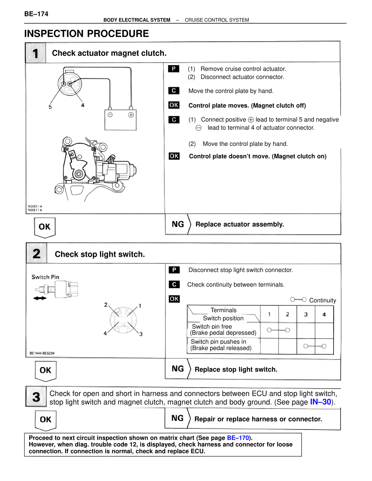
1 Check actuator magnet clutch.
5 4
P (1) Remove cruise control actuator.
(2) Disconnect actuator connector.
C Move the control plate by hand.
OK Control plate moves. (Magnet Clutch off)
C (1) Connect positive ⊕ lead to terminal 5 and negative
⊖ lead to terminal 4 of actuator connector.
(2) Move the control plate by hand.
OK Control plate doesn't move. (Magnet clutch on)
N08514
N08714
OK NG Replace actuator assembly.
2 Check stop light switch.
Switch Pin
2 1
4 3
BE1444 BE6234
P Disconnect stop light switch connector.
C Check continuity between terminals.
OK
O—O Continuity
Terminals
Switch position 1 2 3 4
Switch pin free
(Brake pedal depressed) O—O
Switch pin pushes in
(Brake pedal released) O—O
OK NG Replace stop light switch.
3 Check for open and short in harness and connectors between ECU and stop light switch,
stop light switch and magnet clutch, magnet clutch and body ground. (See page IN–30).
OK NG Repair or replace harness or connector.
Proceed to next circuit inspection shown on matrix chart (See page BE–170).
However, when diag. trouble code 12, is displayed, check harness and connector for loose
connection. If connection is normal, check and replace ECU.