100%
BE–180
BODY ELECTRICAL SYSTEM – CRUISE CONTROL SYSTEM
INSPECTION PROCEDURE
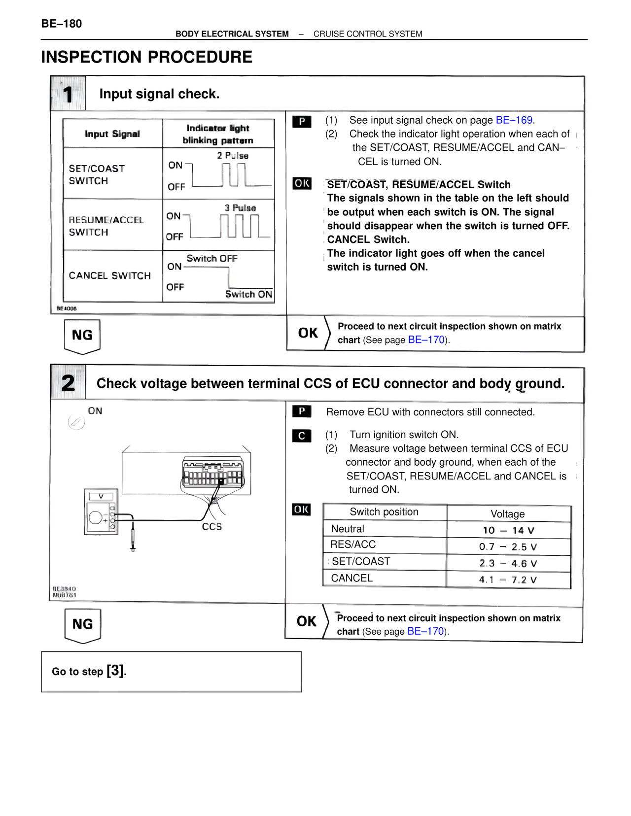
1 Input signal check.
Input Signal Indicator light
blinking pattern
SET/COAST 2 Pulse
SWITCH ON
OFF
RESUME/ACCEL 3 Pulse
SWITCH ON
OFF
CANCEL SWITCH Switch OFF
ON
OFF Switch ON
BE4036
P (1) See input signal check on page BE–169.
(2) Check the indicator light operation when each of
the SET/COAST, RESUME/ACCEL and CAN–
CEL is turned ON.
OK SET/COAST, RESUME/ACCEL Switch
The signals shown in the table on the left should
be output when each switch is ON. The signal
should disappear when the switch is turned OFF.
CANCEL Switch.
The indicator light goes off when the cancel
switch is turned ON.
NG OK Proceed to next circuit inspection shown on matrix
chart (See page BE–170).
2 Check voltage between terminal CCS of ECU connector and body ground.
ON
BE3840
N08761
CCS
P Remove ECU with connectors still connected.
C (1) Turn ignition switch ON.
(2) Measure voltage between terminal CCS of ECU
connector and body ground, when each of the
SET/COAST, RESUME/ACCEL and CANCEL is
turned ON.
OK Switch position Voltage
Neutral 10 – 14 V
RES/ACC 0.7 – 2.5 V
SET/COAST 2.3 – 4.6 V
CANCEL 4.1 – 7.2 V
NG OK Proceed to next circuit inspection shown on matrix
chart (See page BE–170).
Go to step [3].