100%
BE–194
BODY ELECTRICAL SYSTEM – CRUISE CONTROL SYSTEM
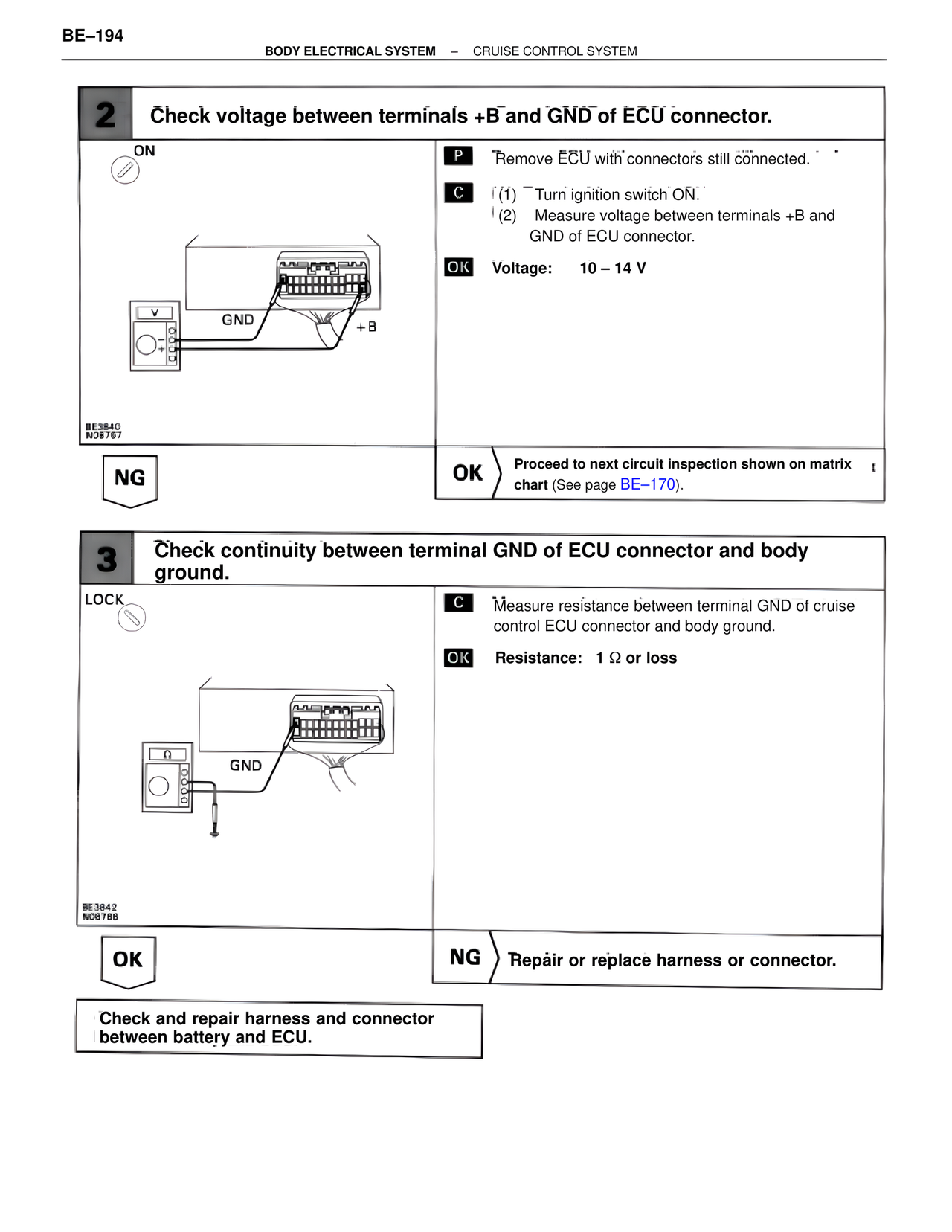
2 Check voltage between terminals +B and GND of ECU connector.
ON
P Remove ECU with connectors still connected.
C (1) Turn ignition switch ON.
(2) Measure voltage between terminals +B and
GND of ECU connector.
OK Voltage: 10 – 14 V
GND +B
BE3840
N08767
NG OK Proceed to next circuit inspection shown on matrix
chart (See page BE–170).
3 Check continuity between terminal GND of ECU connector and body
ground.
LOCK
C Measure resistance between terminal GND of cruise
control ECU connector and body ground.
OK Resistance: 1 Ω or loss
GND
BE3842
N08788
OK NG Repair or replace harness or connector.
Check and repair harness and connector
between battery and ECU.