100%
BODY ELECTRICAL SYSTEM – INTERIOR LIGHT SYSTEM
BE–29
INTEGRATION RELAY INSPECTION
INSPECT RELAY CIRCUIT
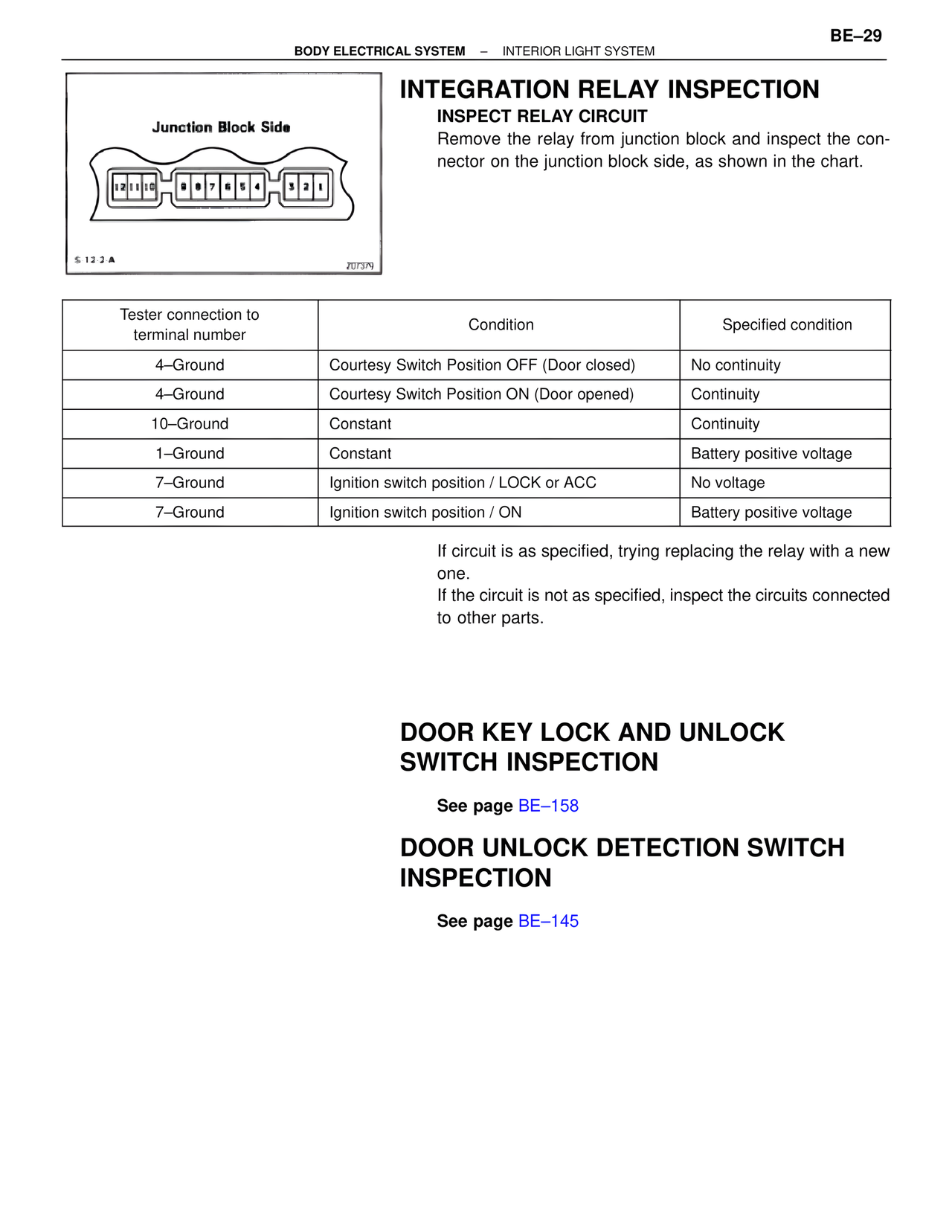
Remove the relay from junction block and inspect the connector on the junction block side, as shown in the chart.
Junction Block Side
12 11 10 9 8 7 6 5 4 3 2 1
S-12-2-A
207379
Tester connection to terminal number | Condition | Specified condition
4–Ground | Courtesy Switch Position OFF (Door closed) | No continuity
4–Ground | Courtesy Switch Position ON (Door opened) | Continuity
10–Ground | Constant | Continuity
1–Ground | Constant | Battery positive voltage
7–Ground | Ignition switch position / LOCK or ACC | No voltage
7–Ground | Ignition switch position / ON | Battery positive voltage
If circuit is as specified, trying replacing the relay with a new one.
If the circuit is not as specified, inspect the circuits connected to other parts.
DOOR KEY LOCK AND UNLOCK SWITCH INSPECTION
See page BE–158
DOOR UNLOCK DETECTION SWITCH INSPECTION
See page BE–145