100%
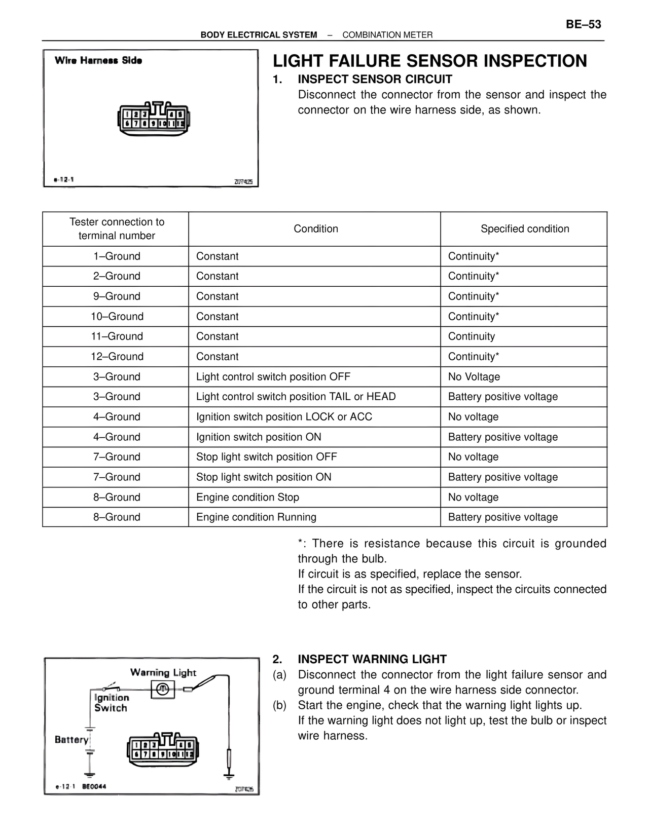
Wire Harness Side
e-12-1
207425
LIGHT FAILURE SENSOR INSPECTION
1. INSPECT SENSOR CIRCUIT
Disconnect the connector from the sensor and inspect the connector on the wire harness side, as shown.
Tester connection to terminal number | Condition | Specified condition
1–Ground | Constant | Continuity*
2–Ground | Constant | Continuity*
9–Ground | Constant | Continuity*
10–Ground | Constant | Continuity*
11–Ground | Constant | Continuity
12–Ground | Constant | Continuity*
3–Ground | Light control switch position OFF | No Voltage
3–Ground | Light control switch position TAIL or HEAD | Battery positive voltage
4–Ground | Ignition switch position LOCK or ACC | No voltage
4–Ground | Ignition switch position ON | Battery positive voltage
7–Ground | Stop light switch position OFF | No voltage
7–Ground | Stop light switch position ON | Battery positive voltage
8–Ground | Engine condition Stop | No voltage
8–Ground | Engine condition Running | Battery positive voltage
*: There is resistance because this circuit is grounded through the bulb.
If circuit is as specified, replace the sensor.
If the circuit is not as specified, inspect the circuits connected to other parts.
Warning Light
Ignition Switch
Battery
e-12-1 BE0044
207426
2. INSPECT WARNING LIGHT
(a) Disconnect the connector from the light failure sensor and ground terminal 4 on the wire harness side connector.
(b) Start the engine, check that the warning light lights up.
If the warning light does not light up, test the bulb or inspect wire harness.