100%
BE-54
BODY ELECTRICAL SYSTEM – COMBINATION METER
OPEN DOOR WARNING INSPECTION
1. INSPECT DOOR COURTESY SWITCH
Switch Position | Tester connection to terminal number | Specified condition
ON (Switch pin released) | 1–2 / 2–3 | Continuity
OFF (Switch pin pushed in) | – | No continuity
If continuity is not as specified, replace the switch.
2. INSPECT WARNING LIGHT
Disconnect the connector from the door courtesy switch, and
ground terminal 1 on the wire harness side connector and
check that the warning light lights up.
If the warning light does not light up, inspect the bulb or wire
harness.
Warning Light
Ignition Switch
Battery
h-3-1-A BE0044
ZD7427
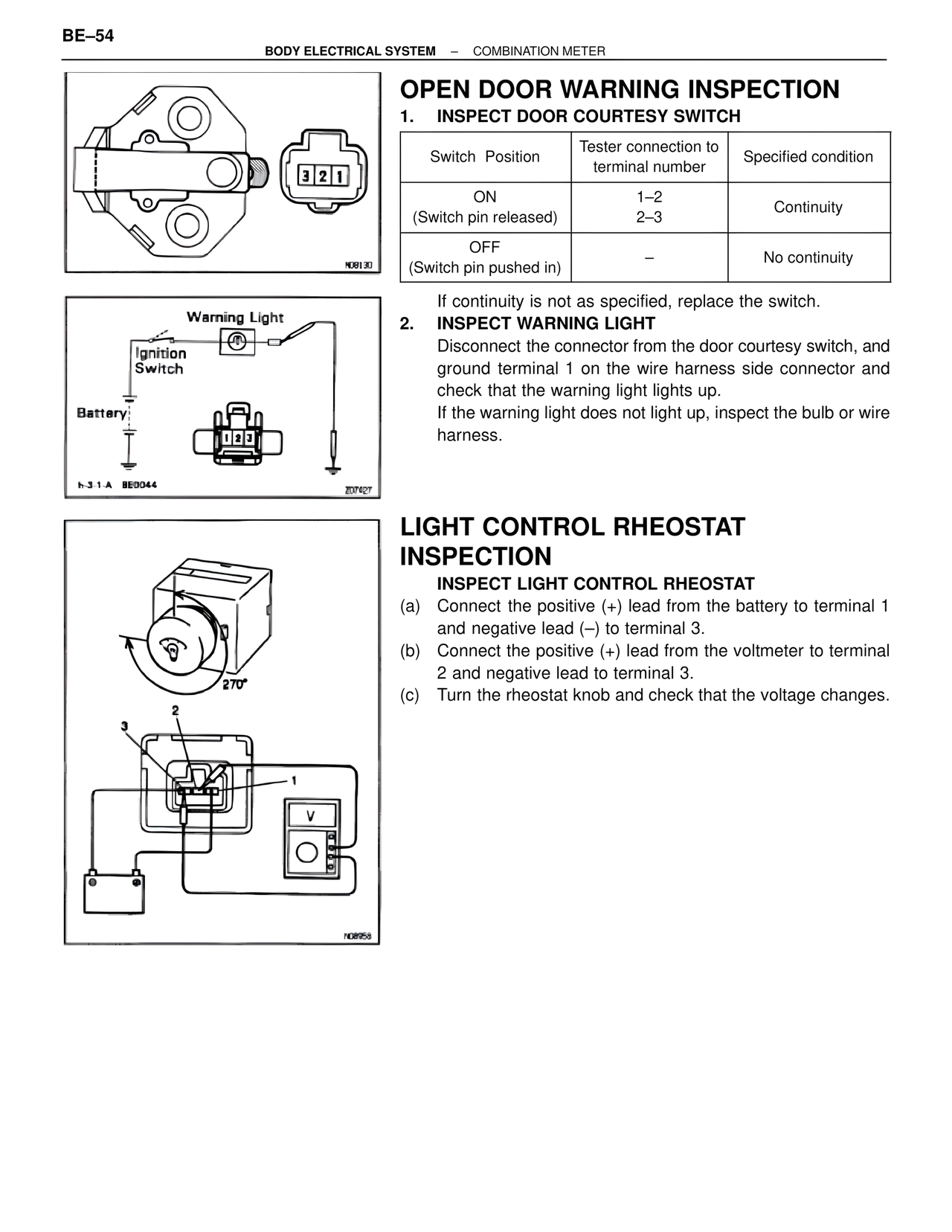
LIGHT CONTROL RHEOSTAT
INSPECTION
INSPECT LIGHT CONTROL RHEOSTAT
(a) Connect the positive (+) lead from the battery to terminal 1
and negative lead (–) to terminal 3.
(b) Connect the positive (+) lead from the voltmeter to terminal
2 and negative lead to terminal 3.
(c) Turn the rheostat knob and check that the voltage changes.
270°
3
2
1
V
N08958
N08130