100%
BODY ELECTRICAL SYSTEM – POWER SEAT CONTROL SYSTEM
BE–75
TROUBLESHOOTING
The table below will be useful for you in troubleshooting these electrical problems. The most likely causes of the malfunction are shown in the order of their probability. Inspect each part in the order shown, and replace the part when it is found to be faulty.
Trouble | Parts name | (See page)
Power seat does not operate
1. POWER Fuse | (BE–5)
2. DOOR Fuse | (BE–6)
3. Wire Harness
4. Power Seat Switch | (BE–75)
"Slide operation" does not operate
1. Power Seat Switch | (BE–75)
2. Wire Harness
3. Sliding Motor | (BE–76)
"Reclining operation" does not operate
1. Power Seat Switch | (BE–75)
2. Wire Harness
3. Reclining Motor | (BE–77)
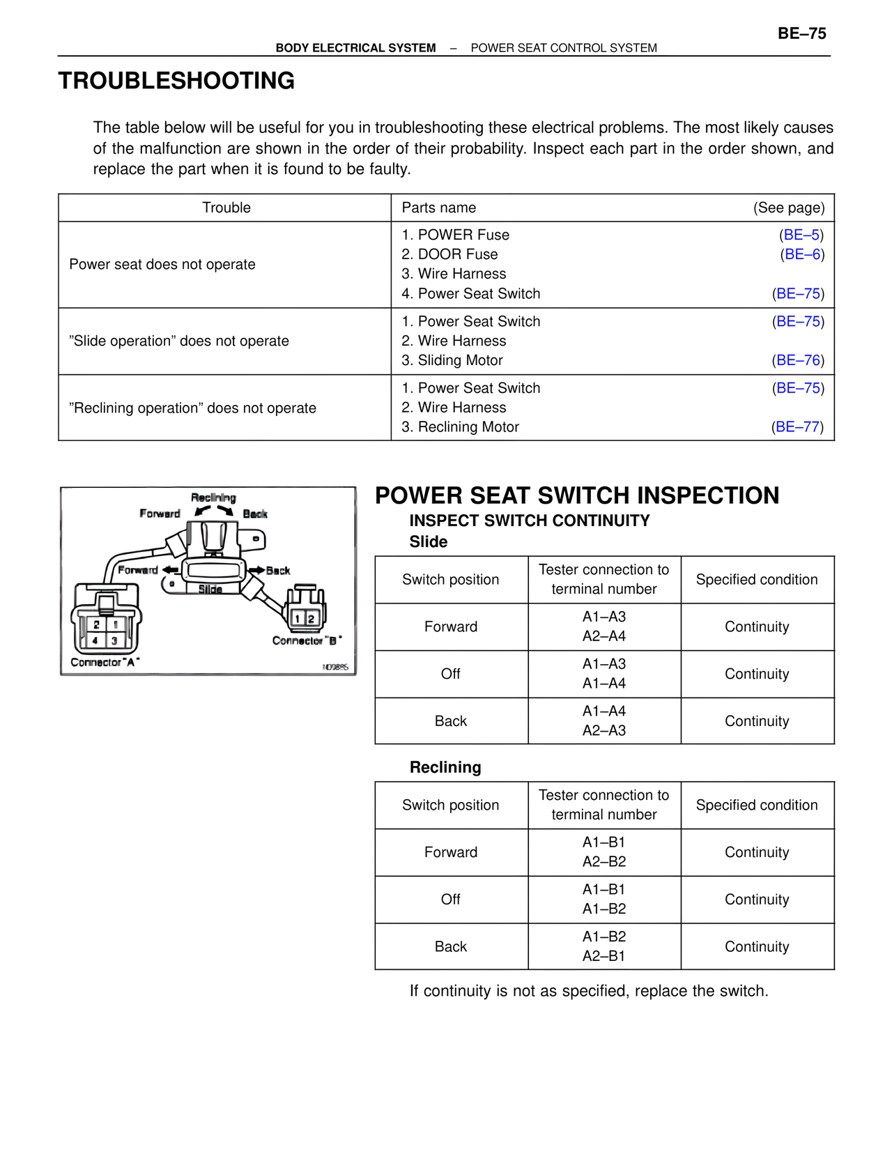
Reclining
Forward Back
Forward Back
Slide
2 1
4 3
Connector "A"
1 2
Connector "B"
ND0885
POWER SEAT SWITCH INSPECTION
INSPECT SWITCH CONTINUITY
Slide
Switch position | Tester connection to terminal number | Specified condition
Forward | A1–A3
A2–A4 | Continuity
Off | A1–A3
A1–A4 | Continuity
Back | A1–A4
A2–A3 | Continuity
Reclining
Switch position | Tester connection to terminal number | Specified condition
Forward | A1–B1
A2–B2 | Continuity
Off | A1–B1
A1–B2 | Continuity
Back | A1–B2
A2–B1 | Continuity
If continuity is not as specified, replace the switch.