100%
ENGINE – COOLING SYSTEM
EG–351
Part "A"
Dimension "B"
SST
Stopper Bolt
Punch Assembly
Overhaul Handle CO1206
5 1 8
3 4
7 2 6
Tank
SST
Lock
Plate
Stopper Bolt
P13075
P02652
Z09523
Tank Rib
Bracket
Pipe
P11771
P11772
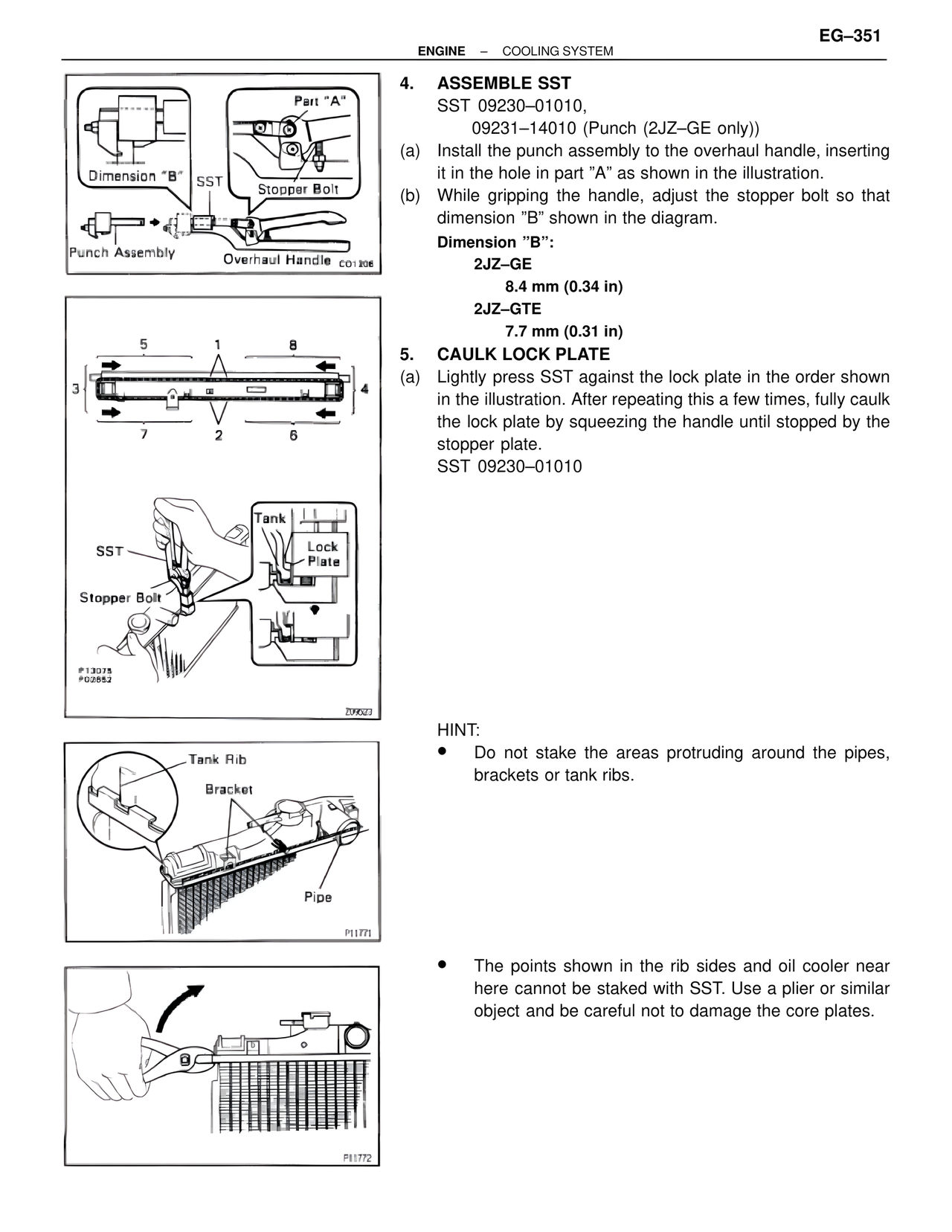
4. ASSEMBLE SST
SST 09230–01010,
09231–14010 (Punch (2JZ–GE only))
(a) Install the punch assembly to the overhaul handle, inserting
it in the hole in part "A" as shown in the illustration.
(b) While gripping the handle, adjust the stopper bolt so that
dimension "B" shown in the diagram.
Dimension "B":
2JZ–GE
8.4 mm (0.34 in)
2JZ–GTE
7.7 mm (0.31 in)
5. CAULK LOCK PLATE
(a) Lightly press SST against the lock plate in the order shown
in the illustration. After repeating this a few times, fully caulk
the lock plate by squeezing the handle until stopped by the
stopper plate.
SST 09230–01010
HINT:
• Do not stake the areas protruding around the pipes,
brackets or tank ribs.
• The points shown in the rib sides and oil cooler near
here cannot be staked with SST. Use a plier or similar
object and be careful not to damage the core plates.