100%
DI-10 BODY DIMENSIONS
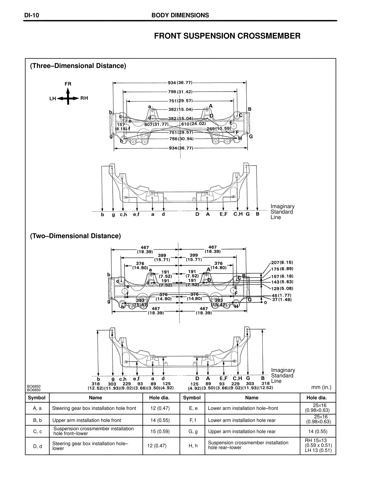
FRONT SUSPENSION CROSSMEMBER
(Three–Dimensional Distance)
FR
LH ←→ RH
934(36.77)
798(31.42)
751(29.57)
a 382(15.04) A
b D B
c d C
157 e 382(15.04) E
(6.18) f 807(31.77) 610(24.02)
751(29.57) 269(10.59)
g F
786(30.94) H
934(36.77)
Imaginary
Standard
Line
b g c,h e,f a d D A E,F C,H G B
(Two–Dimensional Distance)
467
(18.39)
399
(15.71) 467
376 (18.39)
(14.80) a 399
b (15.71)
c 191 376
d (7.52) 191 A(14.80)
191 (7.52) C,B
e (7.52) 191 D
376 (7.52)
f (14.80) 376
g 393 (14.80) 393
h (15.47) (15.47)
467 467
(18.39) (18.39)
207(8.15)
175(6.89)
157(6.18)
143(5.63)
129(5.08)
45(1.77)
37(1.46)
Imaginary
Standard
Line
b g c,h e,f a d D A E,F C,H G B
318 303 229 93 89 125 125 89 93 229 303 318
(12.52)(11.93)(9.02)(3.66)(3.50)(4.92) (4.92)(3.50)(3.66)(9.02)(11.93)(12.52)
BO6850
BO6850 mm (in.)
Symbol Name Hole dia. Symbol Name Hole dia.
A, a Steering gear box installation hole front 12 (0.47) E, e Lower arm installation hole–front 25×16
(0.98×0.63)
B, b Upper arm installation hole front 14 (0.55) F, f Lower arm installation hole rear 25×16
(0.98×0.63)
C, c Suspension crossmember installation 15 (0.59) G, g Upper arm installation hole rear 14 (0.55)
hole front–lower
D, d Steering gear box installation hole– 12 (0.47) H, h Suspension crossmember installation RH 15×13
lower hole rear–lower (0.59 x 0.51)
LH 13 (0.51)